1 Statics Review
All bodies and structures discussed in this text are assumed to be in static equilibrium, which means they experience no acceleration (the sum of all forces and moments are equal to zero). Any body that is not moving or that is moving at constant velocity is in static equilibrium. However, unlike in a standard statics course—where all bodies are assumed to be rigid—in this text bodies are expected to be deformable. This means they may stretch, contract, twist, bend, break, buckle, and so on. To determine how an applied loading situation affects a given body or structure—and potentially causes it to deform—we must first apply statics to establish the distribution of forces and moments within the body. This is the first step of many problems. This chapter reviews those aspects of statics that are prevalent throughout this course.
Section 1.1 reviews the concept of external loads and their representation on free body diagrams.
Section 1.2 reviews equilibrium of structures in two dimensions, including analysis of two-force members and multiforce members.
Section 1.3 addresses internal loads, including normal force, shear force, and bending moment.
Section 1.4 reviews equilibrium in three dimensions.
1.1 External Reactions and Free Body Diagrams
Click to expand
External forces and moments are those that act on the boundaries of a system. They include loads applied to the main structure (weight, wind, pressure, etc.) and the reactions these loads induce in supporting elements (pins, rollers, welds, etc.). In the case of external reactions, the term reaction refers to the forces and/or moments exerted by the supports on the body in response to the applied loading to maintain equilibrium.
Finding the external reactions is the first step in many of the problem types covered in this text. This process begins with drawing a free body diagram (FBD) of the body. An FBD is a sketch of the body “freed” from its supports, showing all the applied and reaction forces and moments to be considered in the analysis. In cases where some loads are insignificant compared to others (e.g., weight sometimes falls into this category), those loads are omitted from the FBD.
The importance of drawing FBDs as a first step in calculating internal and external loads and reactions cannot be overstated. Creating these diagrams establishes which loads and reactions are being included in the analysis, as well as their assumed directions. With the diagrams prepared, you can maintain consistency when summing forces and moments to apply equilibrium equations, helping to ensure accurate results.
Some commonly encountered supports, along with their corresponding reactions and FBD representations, include the following:
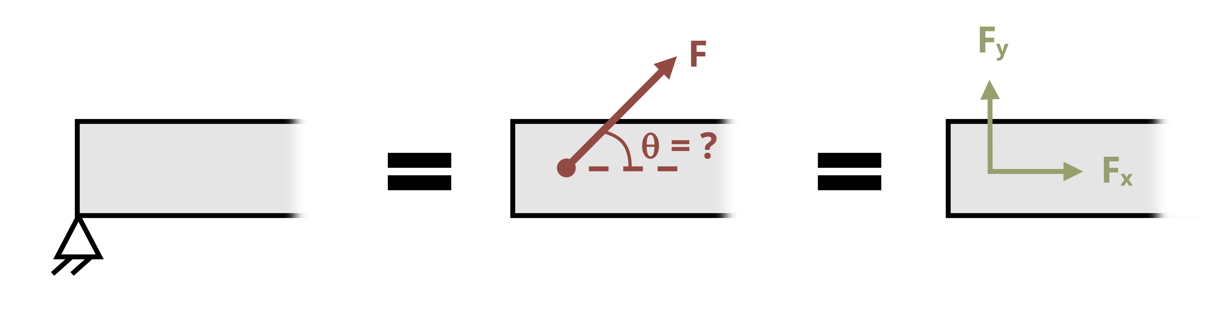
- Pin supports: Pin supports resist any lateral movement of the body relative to the pin at its location. The direction of the overall reaction force (F) is generally unknown, so it is represented as a set of perpendicular force components (Fx and Fy) in the figure below but may also be represented as any set of perpendicular components.
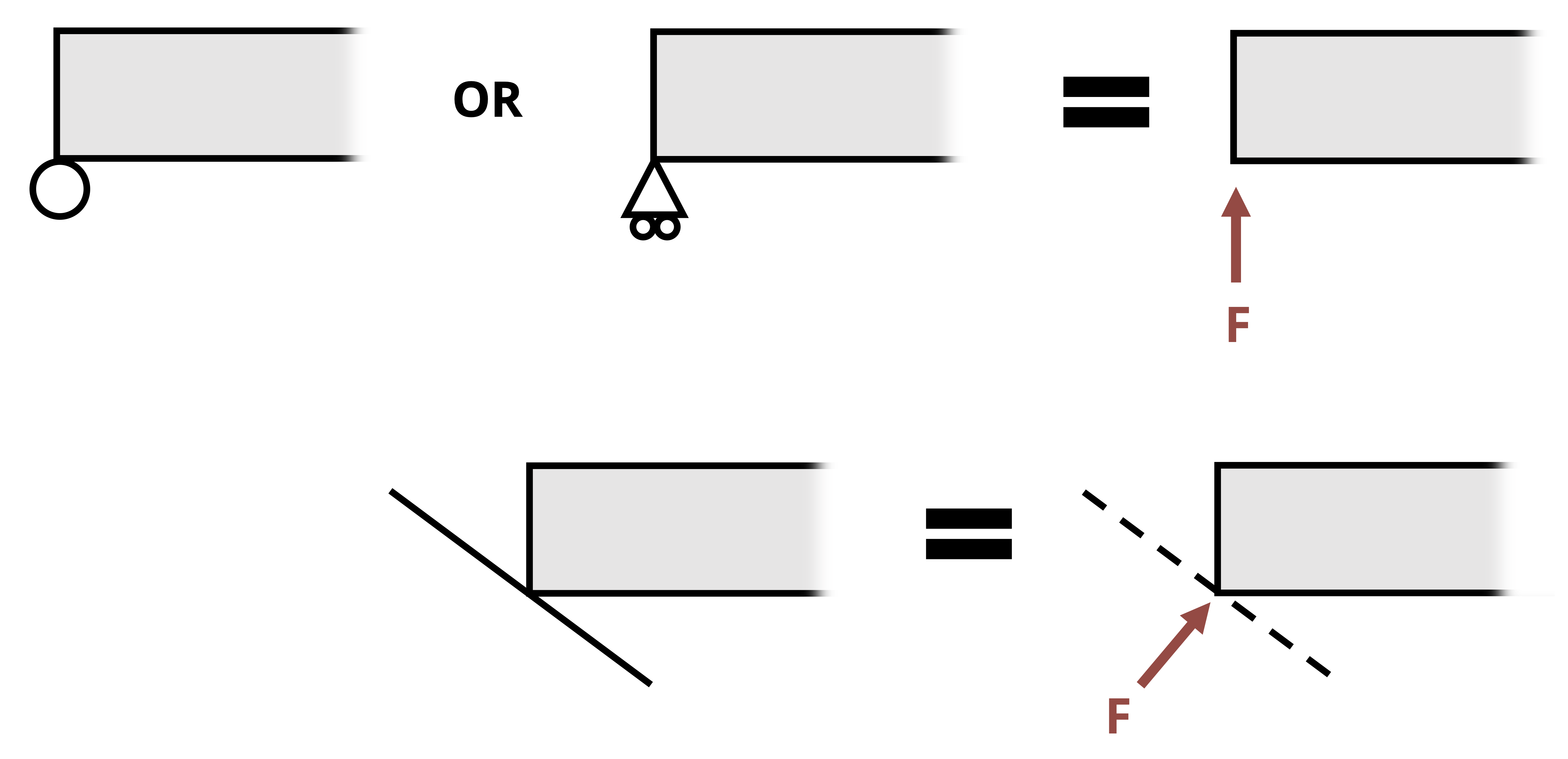
- Normal supports: Normal supports generally consist of surfaces on which the body simply rests (like a beam on a roller) and/or supports that are not fixed to any other surface (like a rocker). Similar to pin supports, normal supports prevent movement of the body relative to the support at its location. However, unlike pins, normal supports prevent only movement in the direction normal to the support site. Consequently, the reaction force (F) acts strictly perpendicular to the supporting surface.
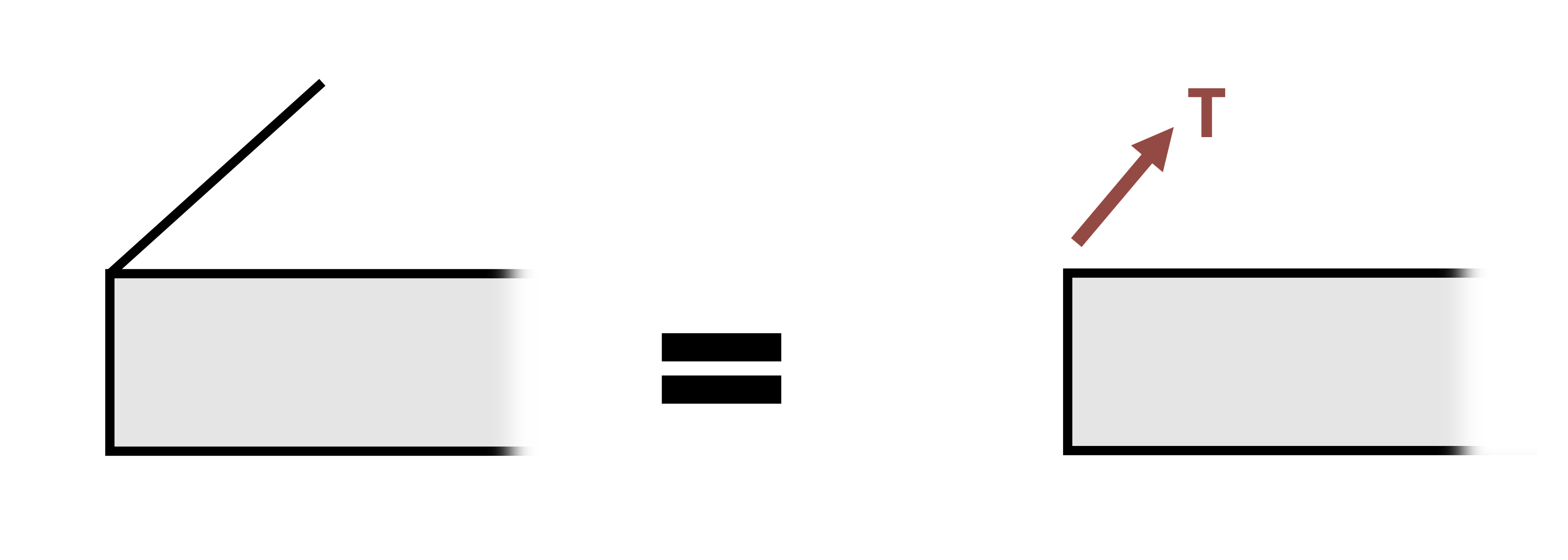
- Cable: A cable provides a tensile force reaction (T). It pulls on the body but never pushes. The reaction force acts in a direction along the path of the cable, extending away from the body and toward the external attachment point.
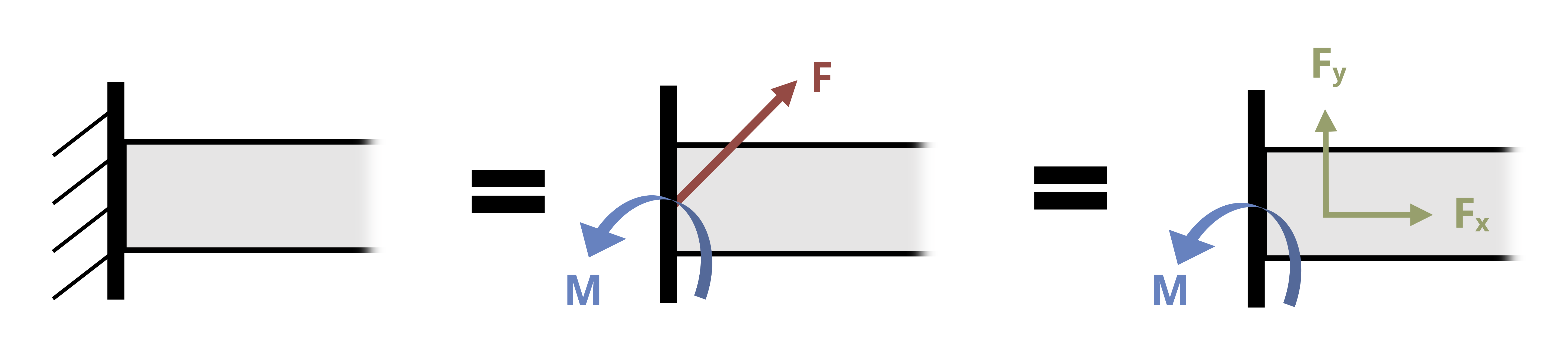
- Fixed support: A fixed support is capable of resisting both lateral movement and rotation, so its reactions consist of a reaction force (F) and a reaction moment couple (M). As with the pinned support, the direction of the overall reaction force is not necessarily known and is therefore represented by a set of perpendicular components. It is important to remember that the reaction moment couple to be solved for is an unknown, just like the reaction force components, and must be included in the moment equation about any point on the body.
Note that when components of the reaction force are found individually, as with the pin support and fixed support, the overall magnitude of the force (F) can be calculated as
\[ F=\sqrt{F_x^2+F_y^2}\text{.} \]
Its direction (i.e., angle measured from the horizontal axis) can be calculated as
\[ \tan \theta_x=\frac{F_y}{F_x}\text{.} \]
Note how the FBDs are drawn in the examples provided throughout this chapter. Geometrical details of a body—such as lengths and angles—are often included on FBDs. However, in this text these features are frequently excluded because they are provided in the problem statement, and the focus here is on representing the loading. You should keep in mind that in some courses and with some instructors these geometrical details may be considered required features of FBDs.
1.2 Equilibrium in Two Dimensions
Click to expand
Once the FBD is drawn, the next step is to apply the equilibrium equations. In two dimensions (x-y plane) these are
\[ \begin{align} \boxed{\sum F_x=0 \quad\sum F_y=0 \quad \sum M_{any~point}=0} \end{align} \tag{1.1}\]
A review of finding moments is given in Section 1.4.
Since there are three equations, a statically determinate problem should have no more than three unknowns.
Example 1.1 illustrates the process of finding external reactions.
Example 1.1 A 3 ft beam is supported by a pin connection at the wall at point A and a cable at point C as shown. A load is applied 2 ft from point A.
Find the force in pin A as well as the tensile force in the cable.
Step 1: Draw the FBD.
The beam is supported with a pin at A, so the support is represented on the FBD with force components Ax and Ay. Note that an assumption must be made about whether Ax points right or left and whether Ay points up or down. The actual directions of Ax and Ay are determined by whether the calculated values are positive or negative. A positive value means the assumed direction was correct, and a negative value means the force acts in the opposite direction.
Cables always exert a force that pulls away from the body. In the FBD below, the cable is represented by force T.
Step 2: Apply equilibrium equations.
If we start with the moment about A equilibrium equation, we can solve for the tensile force T since Ax and Ay do not contribute to the moment about A. Then substituting T into the two-force equilibrium equations allows us to find Ax and Ay.
\[ \begin{aligned}& \sum M_A=T \sin (30^{\circ}) * 3{~ft}-1,200{~lb }*2{~ft}=0\\[10pt]& T = 1,600 {~lb}\\[20pt]& \sum F_x=-A_x-T \cos (30^{\circ})=0\\& -A_x-1,600{~lb} \cos (30^{\circ})=0\\& A_x=-1,385.6{~lb} \\[20pt]& \sum F_y=A_y+T \sin (30^{\circ})-1,200{~lb}=0\\& A_y+1,600{~lb} \sin (30^{\circ})-1,200{~lb}=0\\& A_y= 400{~lb}\end{aligned} \]
Since Ax is negative, it acts in the opposite direction from the assumed direction on the FBD. Thus, Ax acts in the positive x direction.
The total force in pin A is
\[ F_A=\sqrt{A_x^2+A_y^2}=1,442{~lb}\text{.} \]
Answer:
T = 1,600 lb
FA = 1,442 lb
1.2.1 Two-Force Members
One special type of pin connection for which the direction of the reaction force is known is one in which the pin is connected to a two-force member. Contrary to its name, a two-force member is not necessarily a member on which only two forces act. Rather, it is a member where forces are applied at only two distinct locations regardless of how many forces there are. A two-force member can have any shape, as is demonstrated in Figure 1.5. One easy way to recognize a two-force member is by noting the presence of only two pinned points and no other locations where a force or moment couple is applied. Once a member is identified as a two-force member, it can be concluded that the resultant force at both pins is equal in magnitude (FA = FB in Figure 1.5), is opposite in direction, and follows a line of action that goes through the pins. For a straight member, the internal force (discussed in Section 1.3) is equal to the reaction force in the pin.
The presence and recognition of two-force members simplifies equilibrium calculations by reducing the number of unknowns before any computations are performed. This is demonstrated in Example 1.2.
Example 1.2 Determine the force in pin C and in pin A.
Step 1: Draw the FBD.
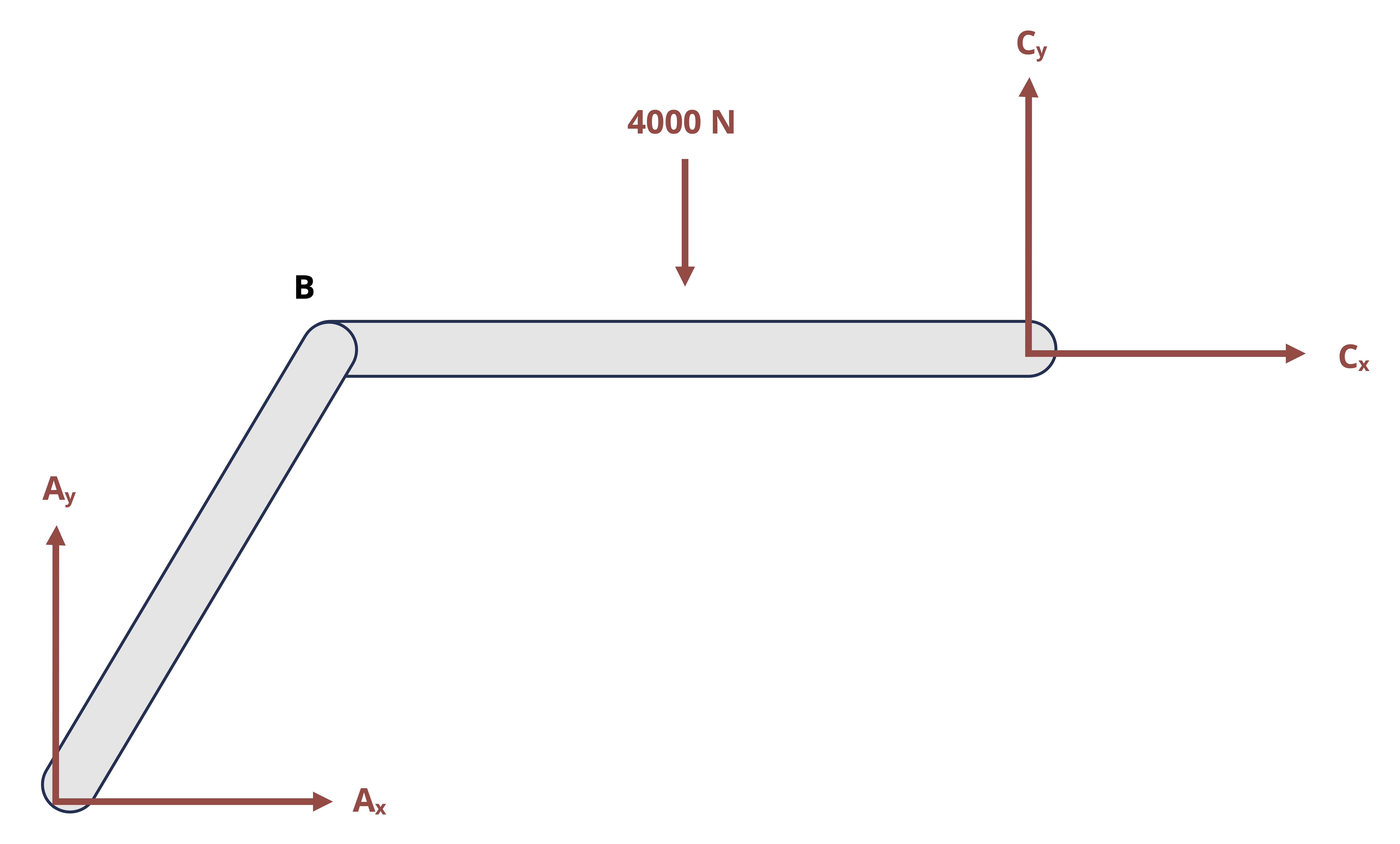
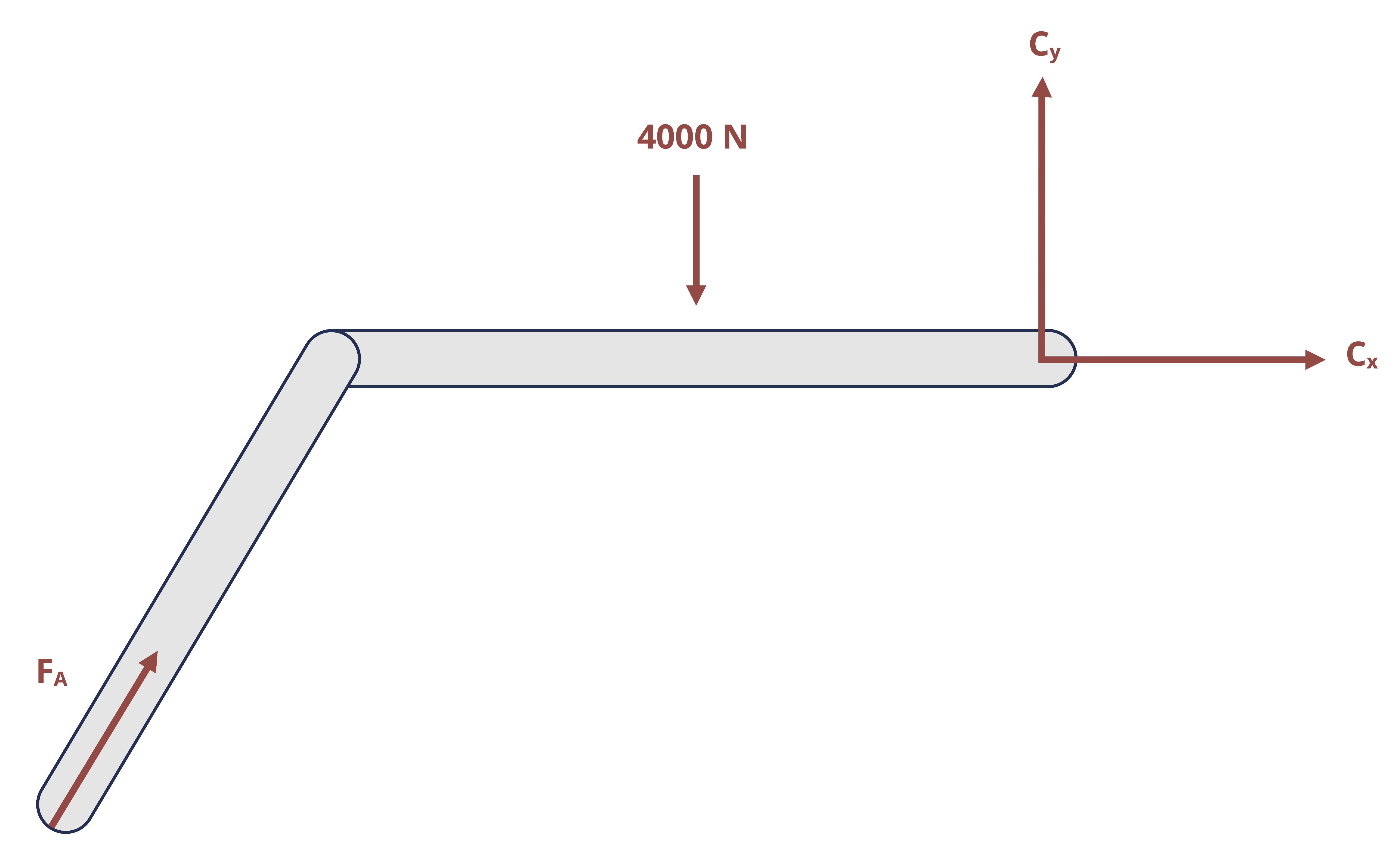
Given this FBD, it appears that there are four unknowns, so it can not be solved with only three equilibrium equations. However, recognizing that bar AB is a two-force member (since there is a pin at A and a pin at B but no other forces acting on that bar), we know that the line of action of the reaction force at A goes through points A and B. Thus, the FBD can be redrawn with only three unknowns.
Step 2: Apply equilibrium equations.
\[ \begin{aligned} & \sum M_C=F_A \cos \left(50^{\circ}\right)*(5{~m}) \sin \left(50^{\circ}\right)-F_A \sin \left(50^{\circ}\right) *\left(4{~m}+5{~m}\left(\cos \left(50^{\circ}\right)\right)+4,000{~ N}*2{~m}=0\right. \\ & \sum F_x=F_A \cos \left(50^{\circ}\right)+C_x=0 \\ & \sum F_y=F_A \sin \left(50^{\circ}\right)-4,000{~N}+C_y=0 \end{aligned} \]
Solving the first equation for FA yields FA = 2,611 N.
Substituting FA into the force equations yields Cx = -1,678 N and Cy = 2,000 N.
Knowing Cx and Cy, we can find the overall pin force FC.
\[ F_C=\sqrt{C_x^2+C_y^2}=2,611{~N} \]
Since Cx is negative, it points in the opposite direction from the assumed FBD. To avoid modifying the FBD, continue assuming the original direction but substitute in the negative value in further calculations.
As an alternative solution (explored in Section 1.3), bar AB and bar BC can be separated by removing the pin at point B and drawing the FBD of bar BC as shown. (Recall that because bar AB is a two-force member, FB goes through points A and B and that FA = FB. We can solve for FA by solving for FB.)
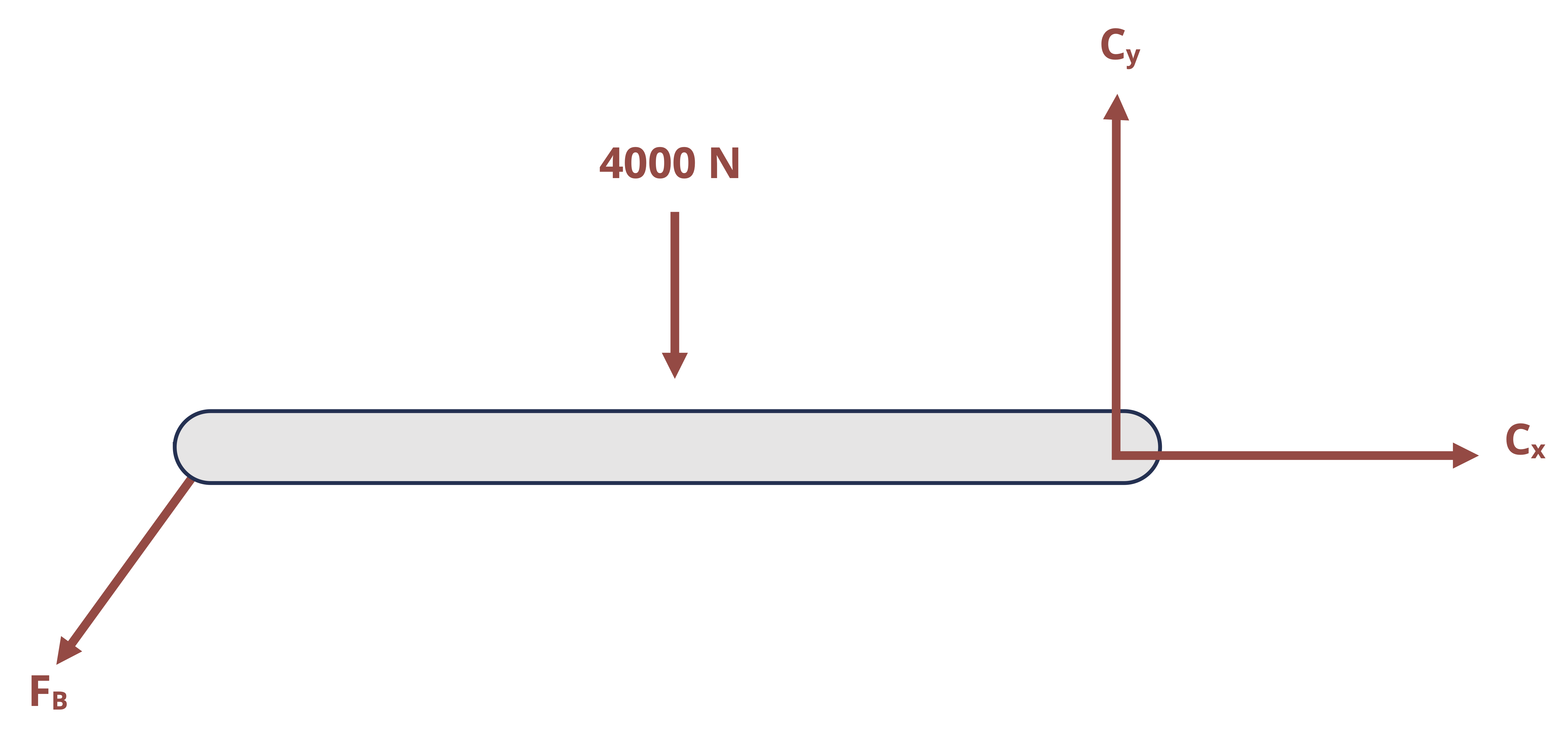
\[ \sum M_C= F_B \sin(50^\circ)*4{~m}+F_B \cos(50^\circ)*0+4,000{~N}*2{~m}=0 \]
This yields the same result: FA = 2,611 N, and the rest of the problem proceeds the same way.
Answer:
FA = 2,611 N
FC = 2,611 N
1.3 Internal Reactions
Click to expand
Internal reactions can be forces and moments at connection points between members (e.g., pins connecting multiple members of a frame, machine, or truss), as well as reactions at any point in a continuous body (e.g., a point in the middle of a beam). These reactions are the forces and/or moments necessary to hold a structure or a body together and are ultimately the loading aspect needed to determine if and how a body will deform or even break.
1.3.1 Internal Reactions at Pinned Connections
An FBD of an entire structure consisting of connected members omits the forces at the connecting pins because the connected members exert equal and opposite forces on each other, and these forces cancel each other in equilibrium equations. The pins that connect the members nonetheless experience reaction forces you must determine to ensure the integrity of the structure. Do the following to find the reaction forces in these internal pins:
Prepare the individual members’ FBDs (imagine the pins pulled out and consider each member separately). With the members disconnected, the reaction forces at the connecting pins no longer cancel each other out in equilibrium equations applied to the individual members. The reaction forces are drawn on the FBDs in the same way as for support pins, described in Section 1.1.
- However, since the connected members do ultimately exert equal and opposite forces on each other, the reaction forces of pins common to two members are drawn in opposite directions on these members’ FBDs.
Given the FBDs, write and solve equilibrium equations for each body. Because three equilibrium equations can be determined for each FBD drawn, one could theoretically solve for three times the number of unknowns.
Note that the FBD of the whole structure may be useful to help solve for some unknowns.
In addition, as discussed, when one of the connected members is a two-force member, the reaction at the pin runs through the points where the forces act on the two-force member.
Example 1.3 and the alternative method used for Example 1.2 demonstrate these concepts.
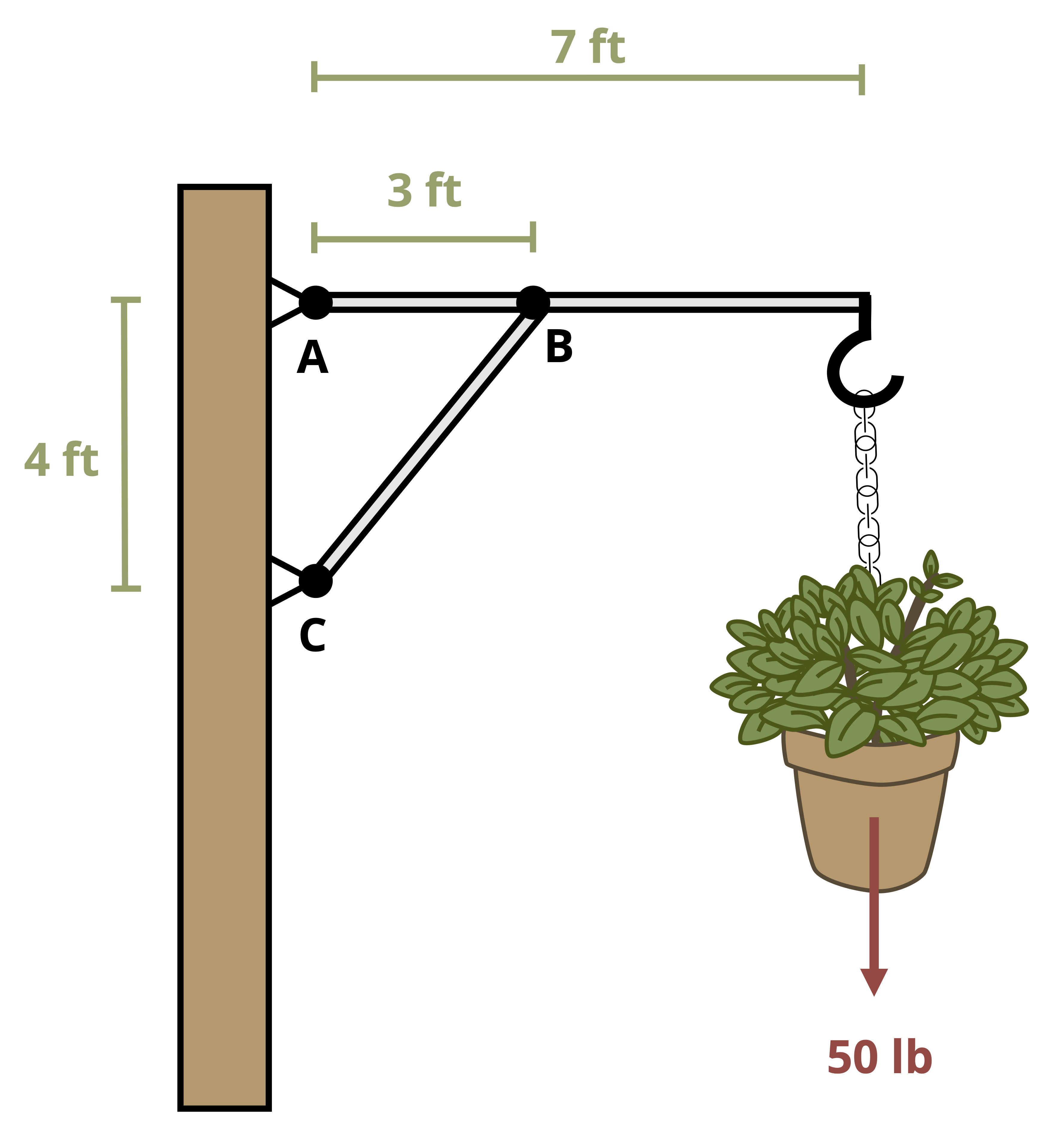
Example 1.3
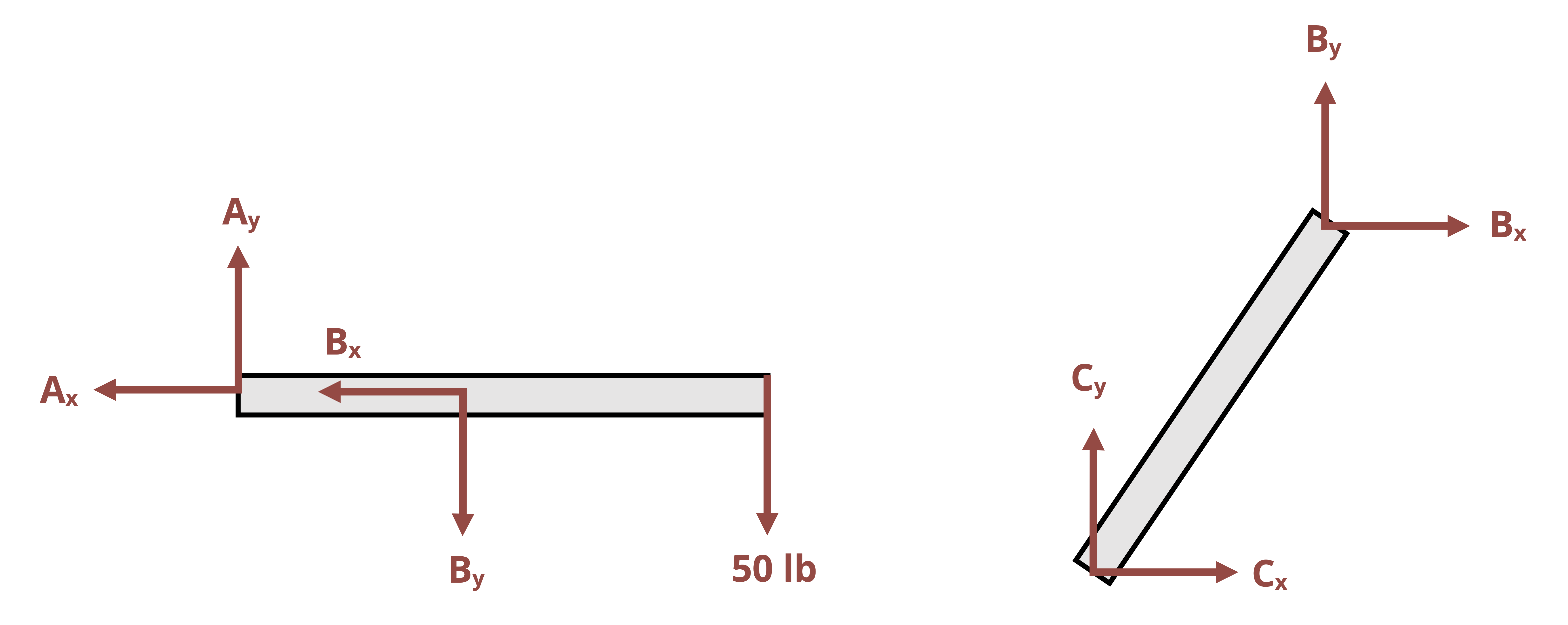
A plant hanger is secured to a wall with a pin and is supported by a pin brace connected to the hanger at B and to the wall at C.
Determine the external reactions at A and C as well as the reaction in the internal pin B.
If BC were not a two-force member, we would approach the problem by separating the brace from the hanger and drawing an FBD of each part separately. Notice that Bx and By are drawn in opposite directions in the two different diagrams because the pin exerts an equal and opposite force on each bar.
Six unknowns and six equilibrium equations (three equations per body) are now available to use per bar, so the problem is technically solvable. However, since BC is a two-force member—there is a pin force at B and a pin force at C but no other forces at any other point on the bar—the reaction force at B follows a line of action that goes through B and C. We can also conclude that the force in pin C is equal to the force in pin B. The FBD of bar AB can be redrawn.
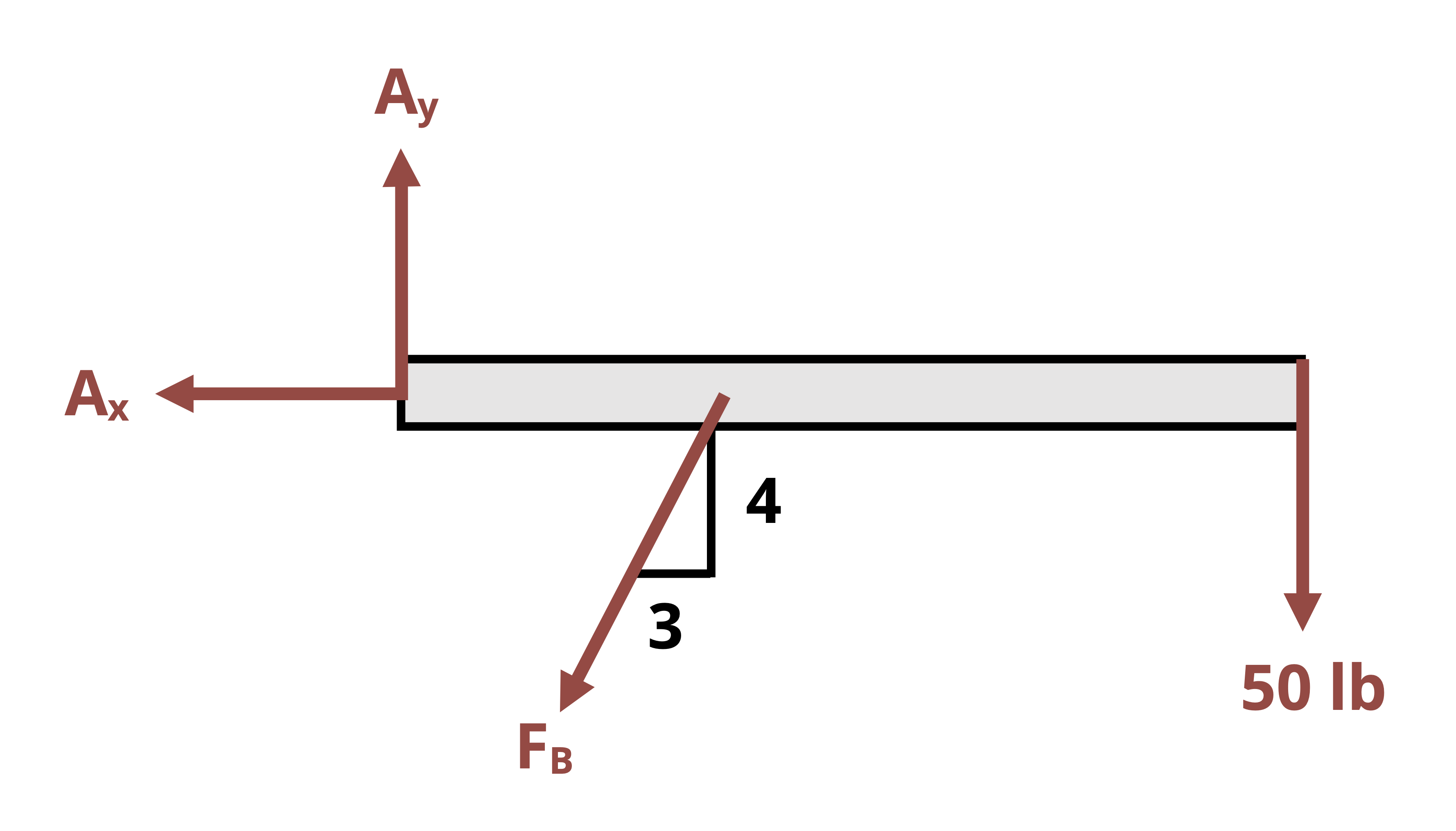
With the components Bx and By replaced with the resultant force FB with known direction, the number of unknowns on bar AB is reduced to three. These unknowns can be solved for using the equilibrium equations.
\[ \begin{aligned} & \sum M_A=F_B\left(\frac{4}{5}\right)*3{~ft}-50{~lb}*7{~ft}=0 \\ & \sum F_x=-A_x+F_B\left(\frac{3}{5}\right)=0 \\ & \sum F_y=A_y+F_B\left(\frac{4}{5}\right)-50{~lb}=0 \end{aligned} \]
Solving the equations yields FB = 145.8 lb, Ax = 87.5 lb, and Ay = -66.7 lb. Therefore, the pin force in pin B is 145.8 lb and the pin force in A is \(\mathrm{A}=\sqrt{A_x^2+A_y^2}=110{~lb}\). Since BC is a two-force member, FC = FB.
Answer:
FA = 110 lb
FB = FC = 146.8 lb
1.3.2 Internal Reactions in Truss Structures
Truss structures are made up of only two-force members. The two main methods of determining internal reactions in planar (2D) truss structures are method of joints and method of sections. In using method of joints, we draw an FBD of the connecting pins (joints) within the truss. Since all the members connected at any given pin will be two-force members, the reactions can be drawn in known directions. However, because the forces all pass through the same point on the body, the moment equilibrium equation is not useful, so only the forces equilibrium equations can be used for each joint. This means that only two unknowns can be solved for at each joint. The method of joints is most useful when the forces of all the truss members are sought or when the only forces sought are attached to a joint with only two members.
To use method of sections, we cut through the truss structure and with the FBD analyze the intact part of the structure either to the left or to the right of the cut. The FBD of either side will show the applied forces and the reaction forces from the cut-through members. These reactions will be equal in magnitude but opposite in direction between the two sides of the cut. The side to examine is usually that which will not require finding external reactions (if there is a free end to the truss) and/or is least complicated to deal with in terms of geometry or applied loads. All three equilibrium equations can generally be effectively applied with method of sections, so three unknowns can be solved for with any given cut. Keep in mind that moments can be taken about points that lie outside the isolated section, which can lead to more efficient solutions.
Example 1.4 demonstrates the use of method of joints and method of sections to solve for forces in truss members.
Example 1.4
Determine the forces in members DE and BE. Let F1 = 8 kN and F2 = 12 kN.
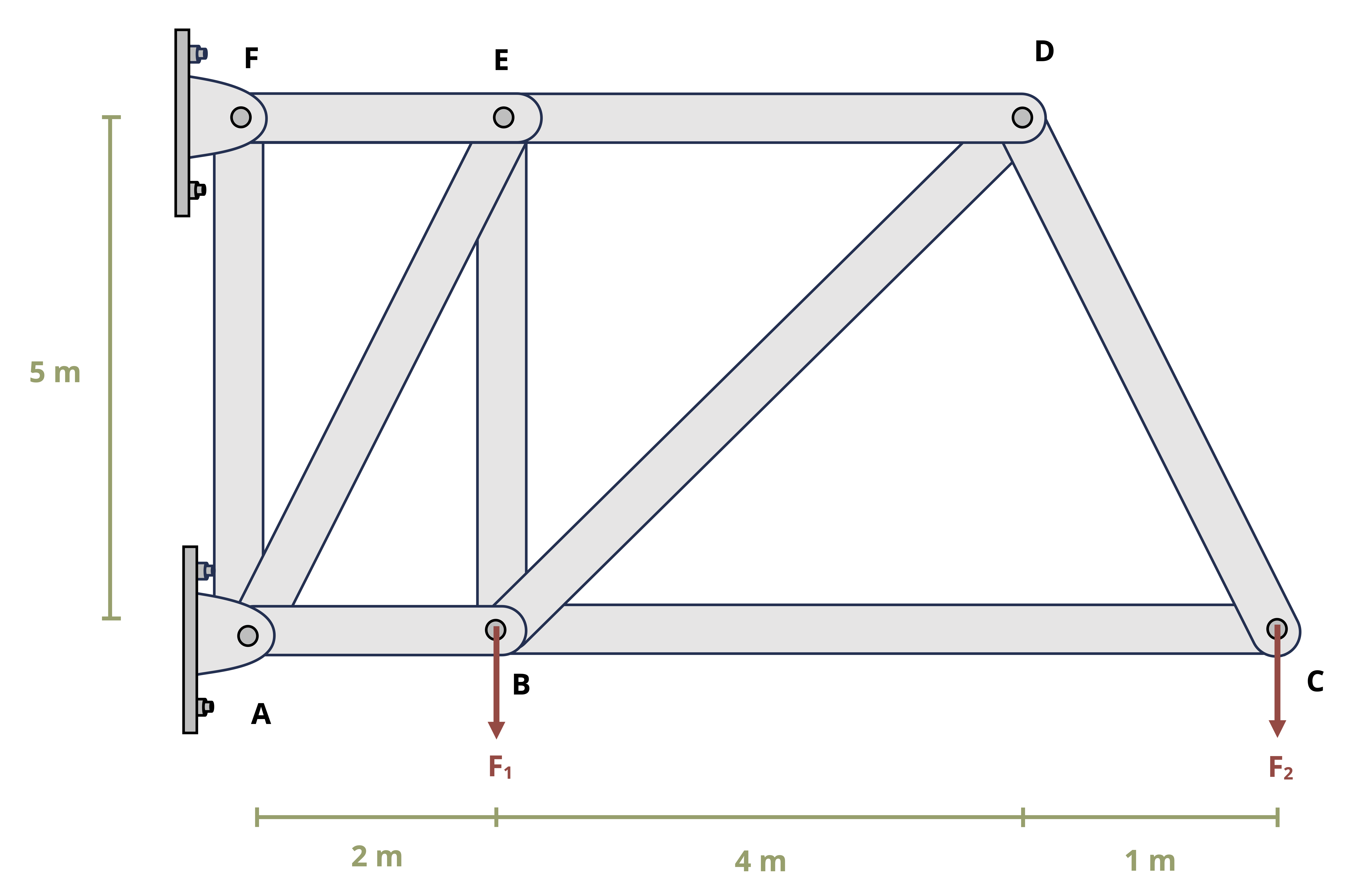
With method of joints, always work with a joint that has no more than two unknown forces acting on it. These unknown forces come either from members attached to the joint or from external support reactions. Joint C is a good place to start here, as there are only two unknown forces: BC and CD.
FBD Joint C
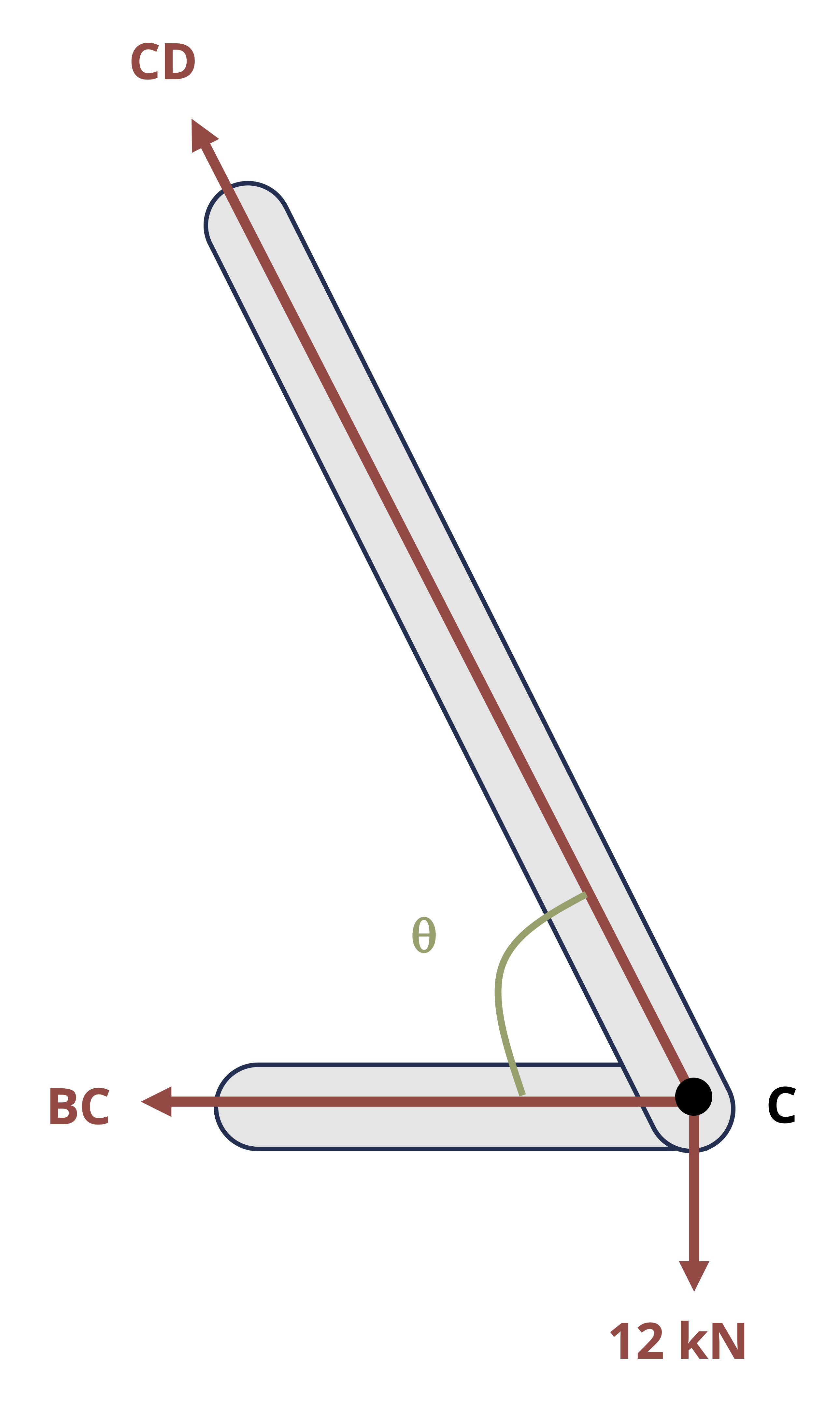
Angle 𝛉 can be found by setting up a right triangle at C with a base of 1 m and a height of 5 m. Once this angle is known, we can use equilibrium equations to find the forces in members BC and CD.
\[ \theta=\tan ^{-1}\left(\frac{5}{1}\right)=78.7^{\circ} \\ \\ \begin{aligned} &\sum F_y=C D \sin \theta-12=0 \quad\rightarrow\quad C D=12.2{~kN} \\ &\sum F_x=-B C-C D \cos \theta=0 \quad\rightarrow\quad B C=-2.4{~kN} \end{aligned} \]
Since the forces in the FBD are shown to be tensile—the forces are pointed away from the joint—the negative answer indicates that force BC is actually compressive.
Now that force CD is known to be 12.2 kN in tension, two unknowns remain at joint D: BD and DE.
FBD Joint D
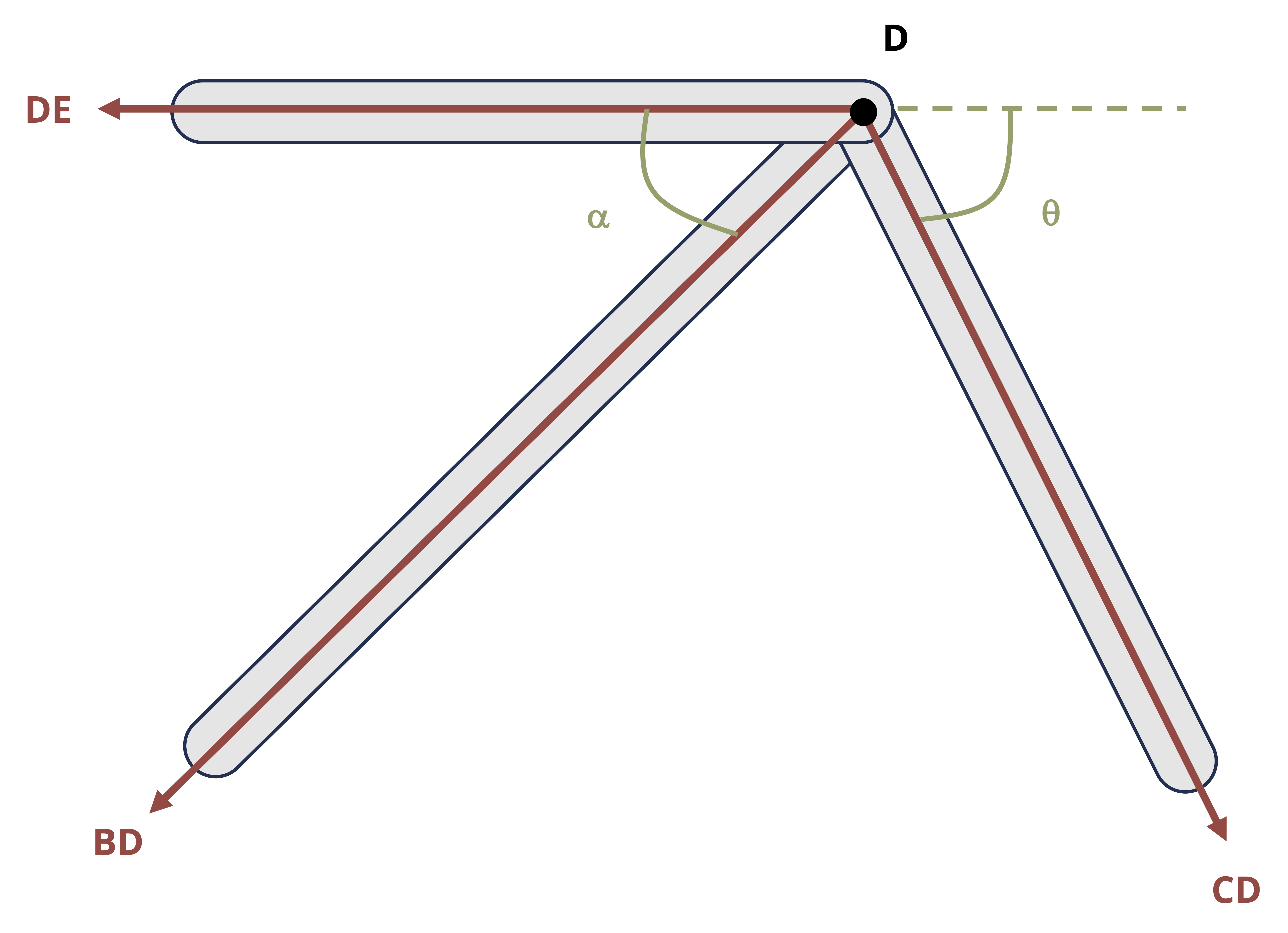
We know the 12.2 kN force acts at an angle of θ = 78.7° from the horizontal. Angle ⍺ can be found by considering right-angle triangle BDE, which has a base of 4 m and a height of 5 m. Once this angle is known, we can use equilibrium equations to find the forces in members BD and DE.
\[ \alpha=\tan ^{-1}\left(\frac{5}{4}\right)=51.3^{\circ} \\ \\ \begin{aligned} \sum F_y&=-B C \sin \theta-B D \sin \alpha=0 \quad \\ &=-12.2 \sin \left(78.7^{\circ}\right)-B D \sin \left(51.3^{\circ}\right)=0 \quad\rightarrow\quad B D=-15.4{~kN} \\ \sum F_x&=-D E-B D \cos \left(\alpha\right)+12.2 \cos (\theta)=0 \\ &=-D E-(-15.4\ kN) \cos \left(51.3^{\circ}\right)+12.2\ kN\cos \left(78.7^{\circ}\right)=0 \quad\rightarrow\quad D E=12{~kN} \end{aligned} \]
Force BD is 15.4 kN in compression and force DE is 12 kN in tension. Now we need to find force BE. Two unknowns remain at joint B: AB and BE.
FBD Joint B
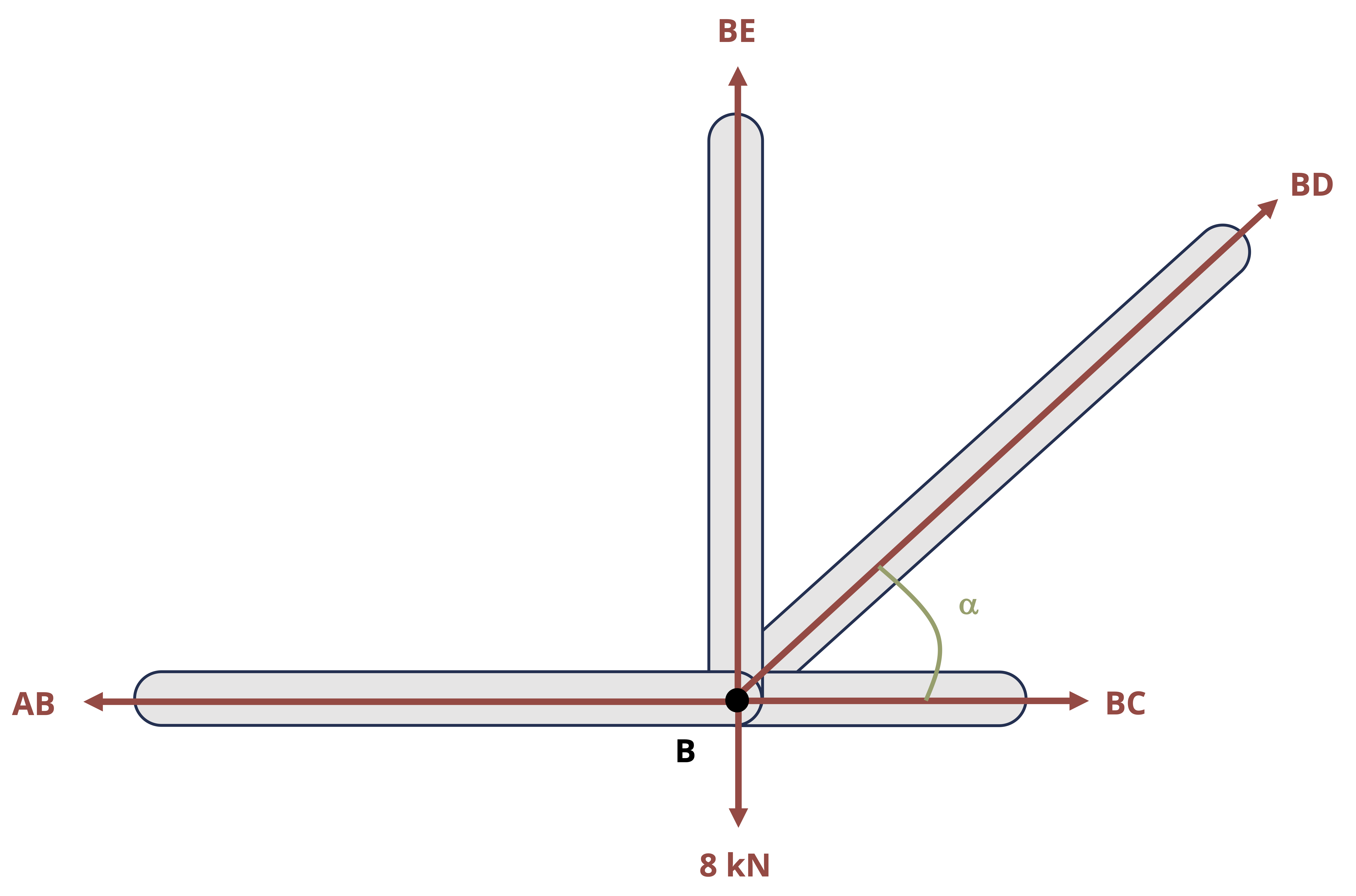
\[ \begin{aligned}\sum F_y&=B E-8+B D \sin \alpha=0 \quad \\&=B E-8+(-15.4) \sin \left(51.3^{\circ}\right)=0 \quad\rightarrow\quad B E=20{~kN} \\\end{aligned} \]
Answer:
DE = 12 kN (Tensile)
BE = 20 kN (Tensile)
Although method of joints can be used here, it is an inefficient approach requiring us to draw and analyze FBDs of joints C, D, and B as well as to keep track of the forces at these joints and whether each force is in tension or compression.
As an alternative, we may use method of sections to find forces BE and DE. To apply this method, cut through no more than three unknown members and draw an FBD with no more than three total unknowns. For this problem, make a cut through the truss that passes through members AB, BE, and DE.
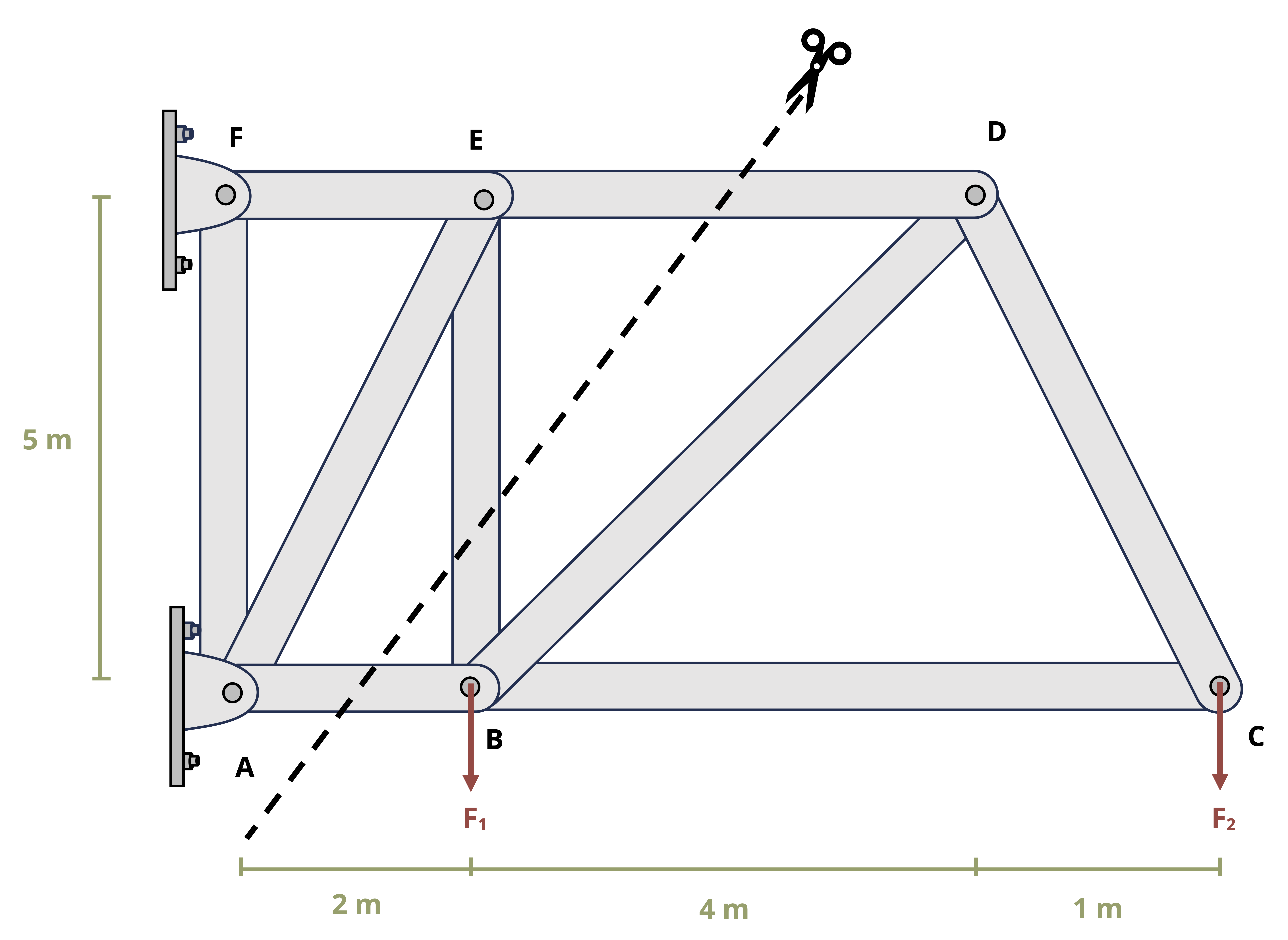
Once that cut is made, draw an FBD for the intact part of the truss either to the left or to the right of the cut. The external forces on the chosen side and the force of each cut-through member need to be shown on the FBD.
If we chose the left side, there would be unknowns AB, BE, and DE as well as unknown reactions Ax, Fx, and Fy. However, the right side would have no unknown support reactions, so the only unknowns are forces AB, BE, and DE.
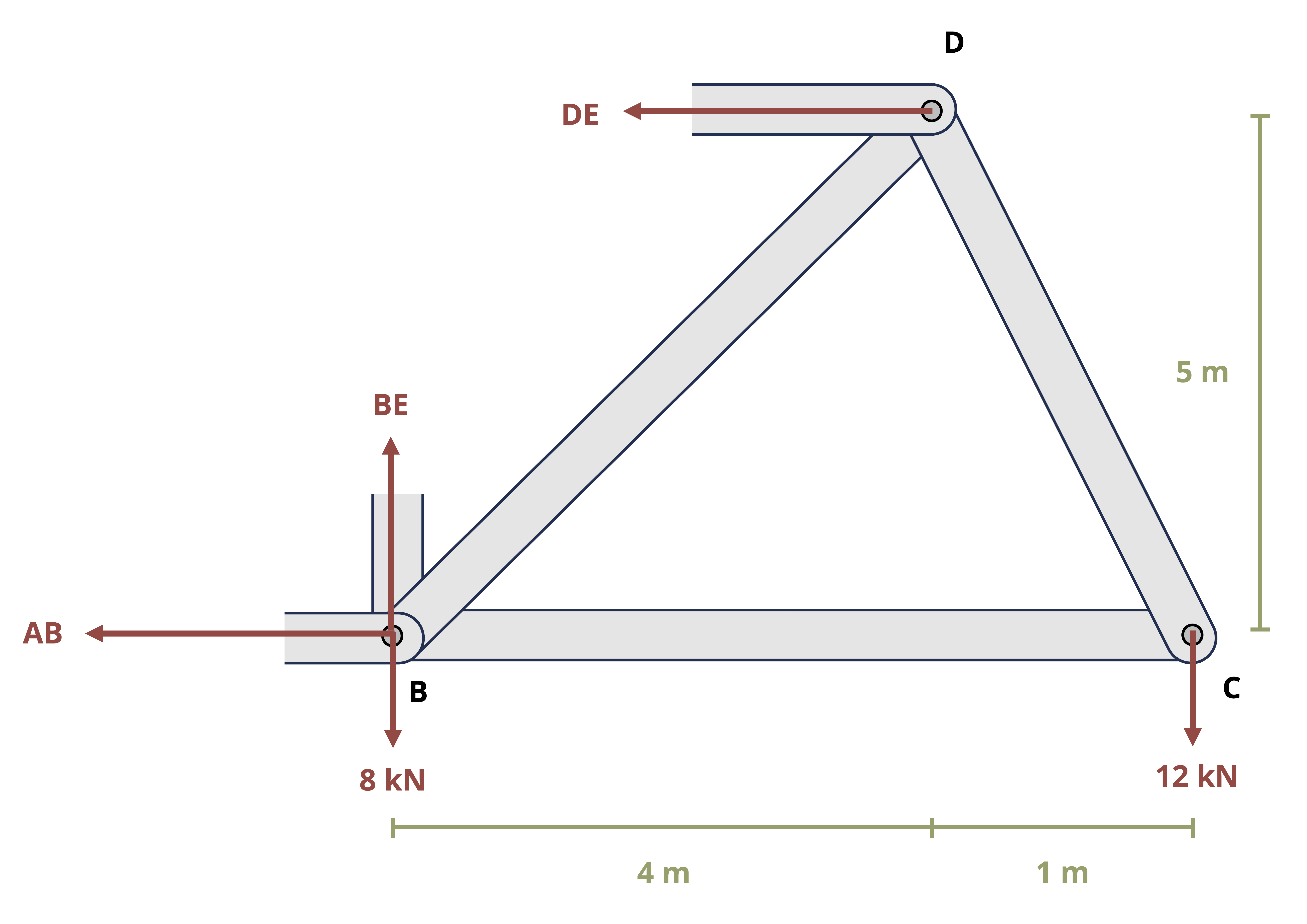
\[ \begin{aligned} & \sum M_B=-(12*5)+(DE*5)=0 \quad\rightarrow\quad D E=12{~kN} \\ & \sum F_y=BE-8-12=0 \quad\rightarrow\quad B E=20{~kN} \end{aligned} \]
Once again the forces are drawn on the FBD in the tensile direction. The positive answers confirm that the forces are indeed tensile.
Answer:
DE = 12 kN (Tensile)
BE = 20 kN (Tensile)
1.3.3 Internal Reactions in Continuous Bodies
Internal reactions also exist within a body or structure. These reactions are necessary to hold the body together and vary from point to point in a body depending on the distribution of external loading. As shown in Figure 1.6, the reactions at any given point can be examined by making a cut at the point of interest in the body. Think of any point within a body as acting as a fixed support for the rest of the body. That is, every point must potentially exert a force parallel to the cross section where the cut is made, which is the shear force V; a force perpendicular to the cross section where the cut is made, which is the normal force N; and a reaction moment where the cut is made, which is the bending moment M. Moreover, as discussed for internal pin reactions and the cut made for method of sections for trusses, the reactions at a cut will be equal and opposite on the two sides of the cut.
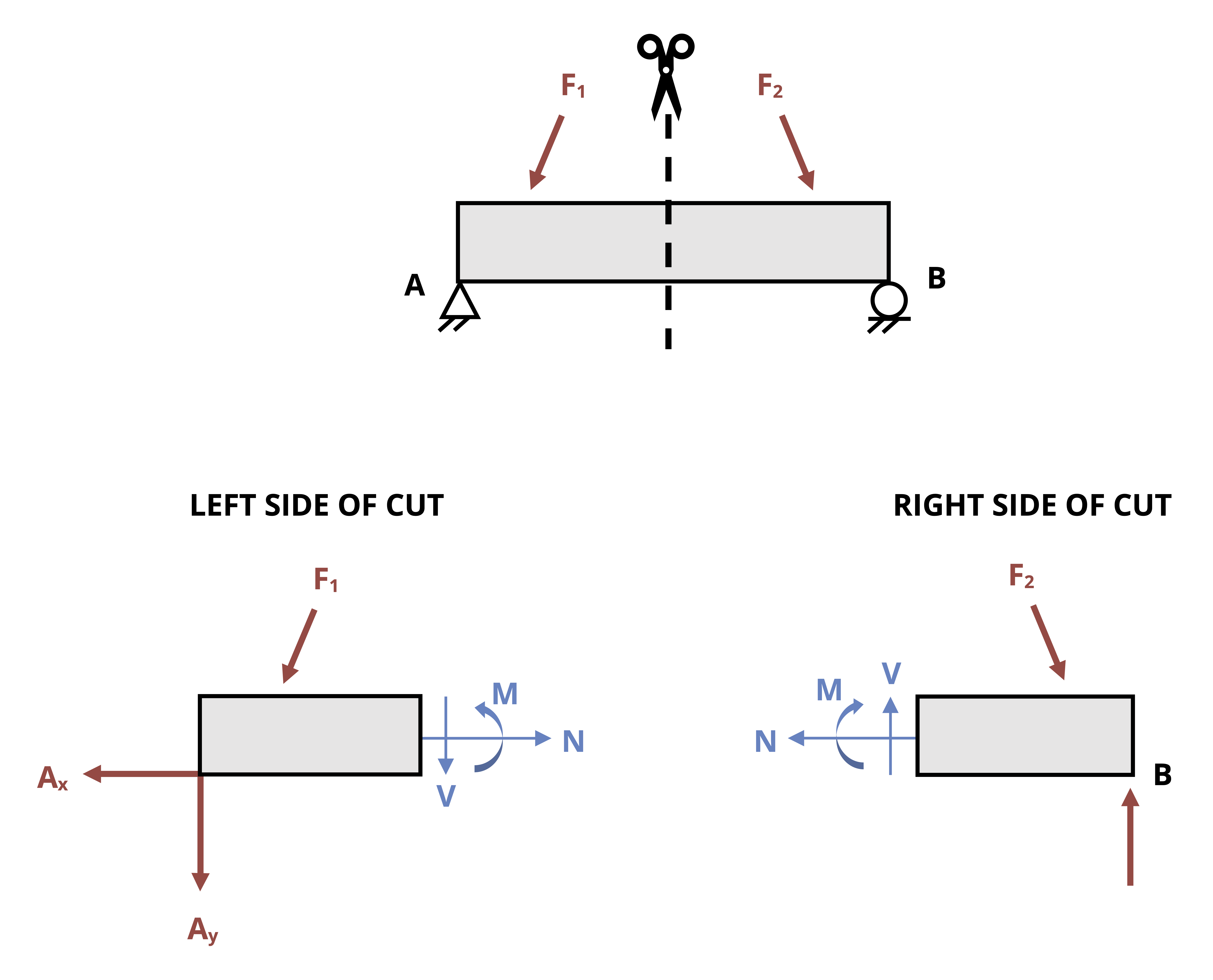
To determine the reactions, draw and use the FBD of the part of the beam either to the left or to the right of the cut. As with method of sections for trusses, choose which side of the cut to examine primarily by determining which side appears easiest and most efficient to analyze. Once the FBD of the cut section is drawn, the three equilibrium equations can be applied to determine the internal reactions. The determination of shear and bending moments in beams is reviewed in more detail in Chapter 7. The focus of Example 1.5 is on the determination of the normal force, as this is important in Chapter 2 and Chapter 3.
Example 1.5
Two solid bars make up the axial assembly loaded as shown.
Determine the normal force in each bar. State whether the force is tensile or compressive.
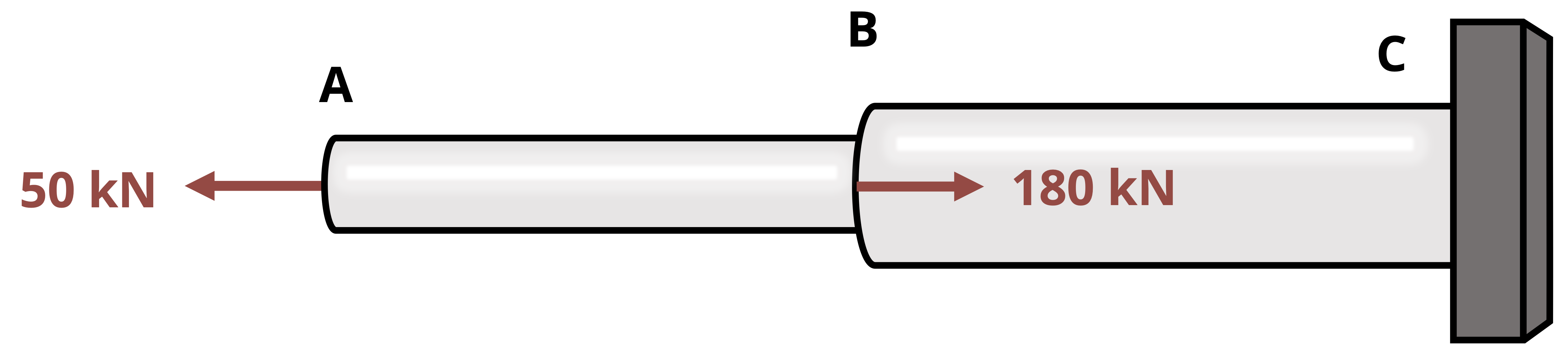
Though the assembly is not a beam, determining the internal reactions works in the same way. In this particular case, all the forces are in the normal direction (no shear force). Furthermore, because of the central placement of the 50 kN and 180 kN forces, there is no bending moment. Consequently, only the normal reaction force is drawn on the FBDs.
To find the internal load in a segment, cut a cross-section within that segment. Since the external loading (and therefore the internal loading) changes at point B, make one cut in segment AB and another in segment BC.
Making the cut in section AB and drawing the FBD allow us to determine the normal force in section AB. Drawing the FBD of the left section of the cut allows us to avoid needing to know the external reactions at wall C.
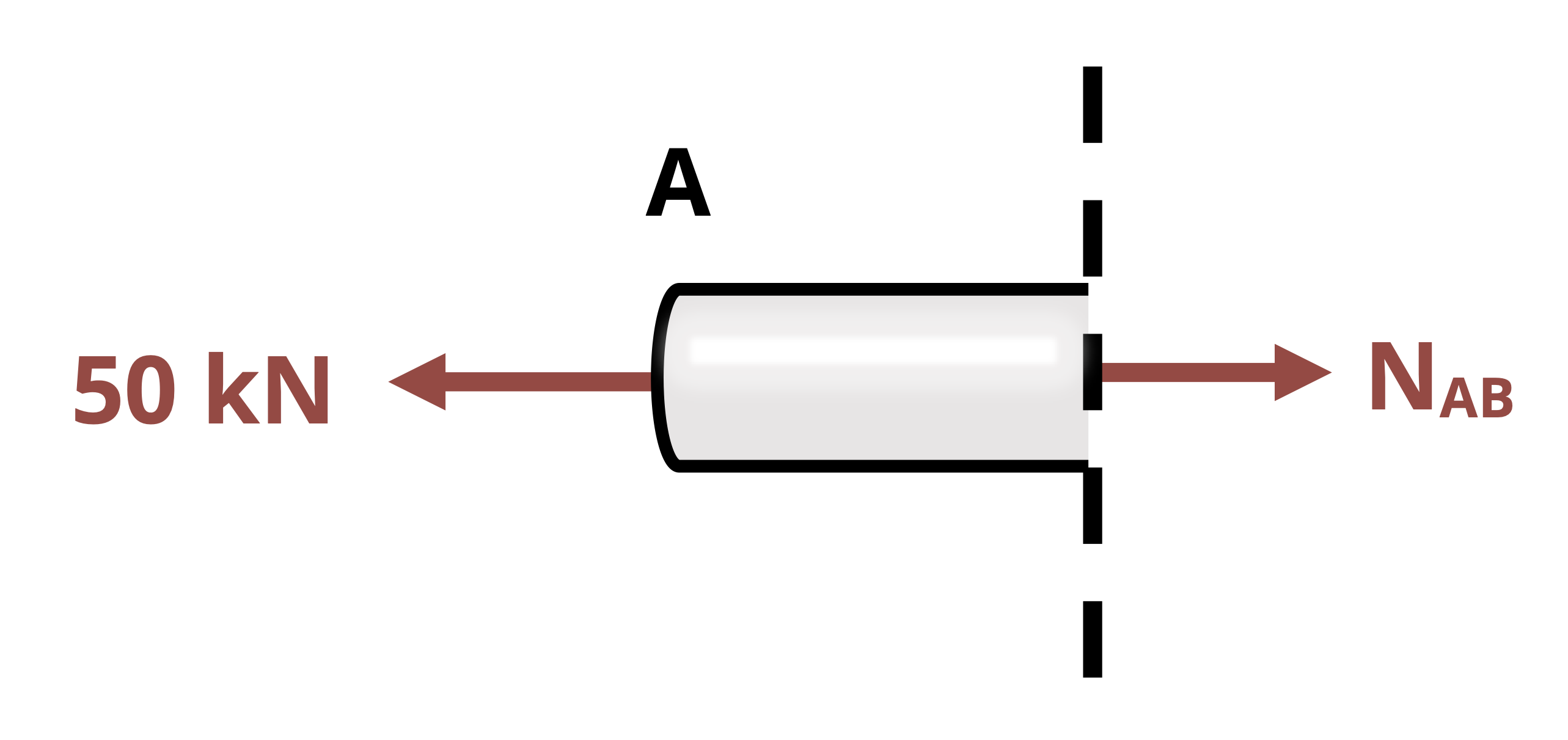
\[ \sum F_x=-50{~kN}+N_{AB}=0 \quad\rightarrow\quad N_{AB}=50{~kN} \]
Making the cut in section BC and drawing the FBD allows us to determine the normal force in section BC. Once again draw the side to the left of the cut to avoid needing the reaction at the wall.
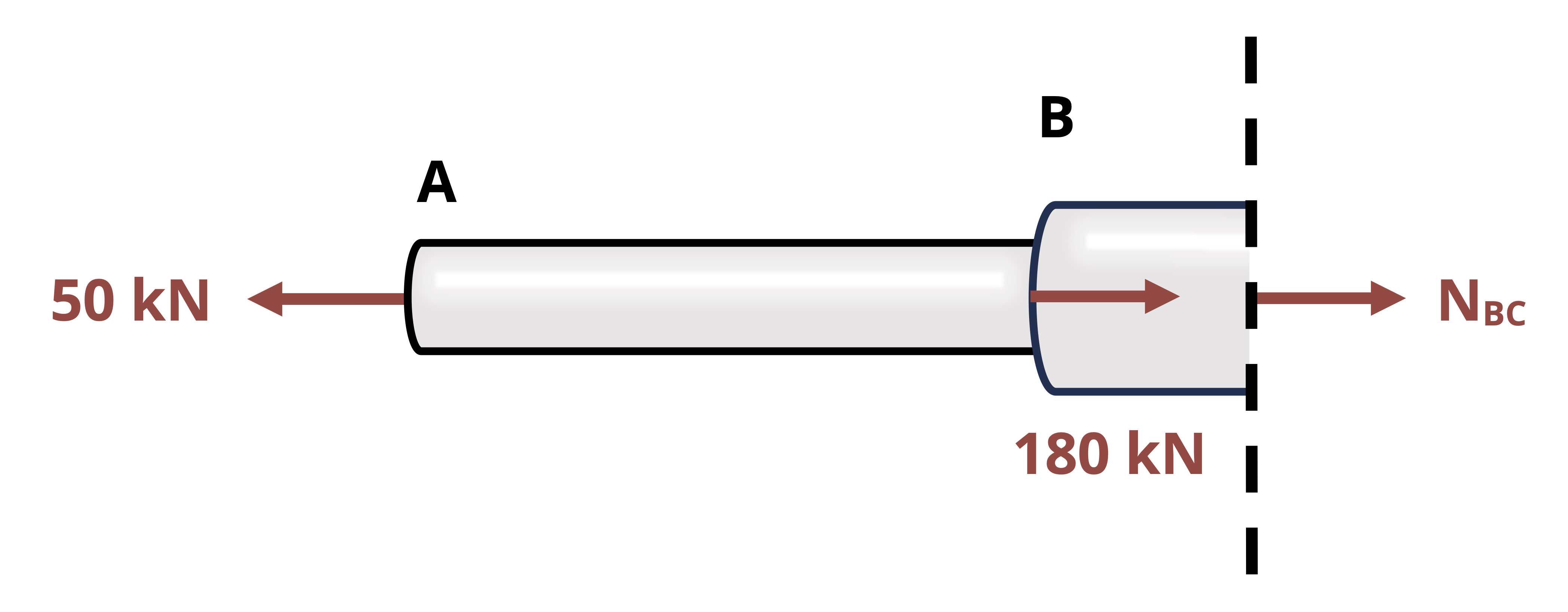
\[ \sum F_x=-50{~kN}+180{~kN}+N_{BC}=0 \quad\rightarrow\quad N_{BC}=-130{~kN} \]
For both AB and BC, the internal normal force was assumed tensile in the FBD and equilibrium equation. In the case of NAB, the positive answer confirms that it is tensile. In the case of NBC, the negative answer reveals that it is compressive.
Answer:
NAB = 50 kN (Tensile)
NBC = 130 kN (Compressive)
1.4 Equilibrium and Reactions in Three Dimensions
Click to expand
While we can often model structures as two dimensional, as in the previous examples, many real-life structures are subjected to forces and moments in all directions, necessitating the consideration of three-dimensional forces and three-dimensional moments. The process of finding external and internal reactions is the same in 3D as in 2D, but there are three additional equilibrium equations and three additional reactions.
For 3D systems there are six total scalar equilibrium equations as shown.
\[ \boxed{\begin{array}{ll} \sum F_x=0 &\;\;\; \sum M_x=0 \\ \sum F_y=0 &\;\;\; \sum M_y=0 \\ \sum F_z=0 &\;\;\; \sum M_z=0 \end{array}} \tag{1.2}\]
Recall that the moment vector describes the axis around which the body tends to rotate. Each individual component represents the tendency of the body to rotate around the specified axis.
In 3D there are three internal forces and three internal moments (Figure 1.7). One normal force (Nx) is perpendicular to the cross-section, and two shear forces (Vy and Vz) are parallel to the cross-section. Two bending moments (My and Mz) act around the axes parallel to the cross-section, and one torsional moment (Tx) acts around the axis perpendicular to the cross-section. This textbook examines each of these loads.
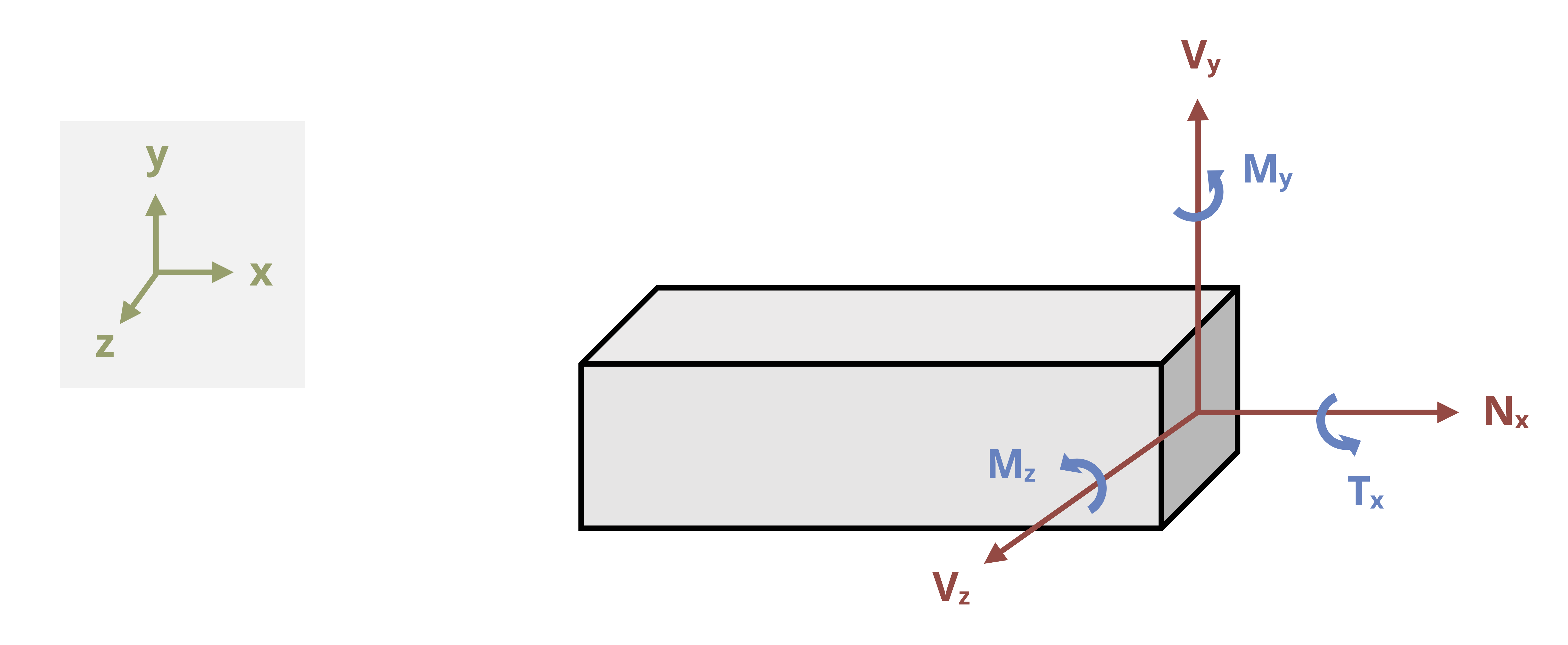
Note that here the choice of coordinate system is arbitrary (as long as it is a right handed coordinate system). Loads are defined as normal, shear, bending, or torsional according to the effect they have on the body. For example, the normal force always acts in the direction perpendicular to the cross-section of the body and has the effect of extending or compressing the body. In the case of Figure 1.7, the x-axis is the axis perpendicular to the cross-section, so the force in the x direction is the normal force. If the axes or the body were oriented differently, the x component of the force could be a shear force instead of a normal force.
While summing the reaction forces in 3D is a straightforward process of adding forces in each direction, summing moments in 3D can prove to be more complicated. To sum moments, there are generally two options. One option is to use the cross product to calculate moments: \(\vec M=\vec r \times \vec F\).
1.4.1 Calculating Moments
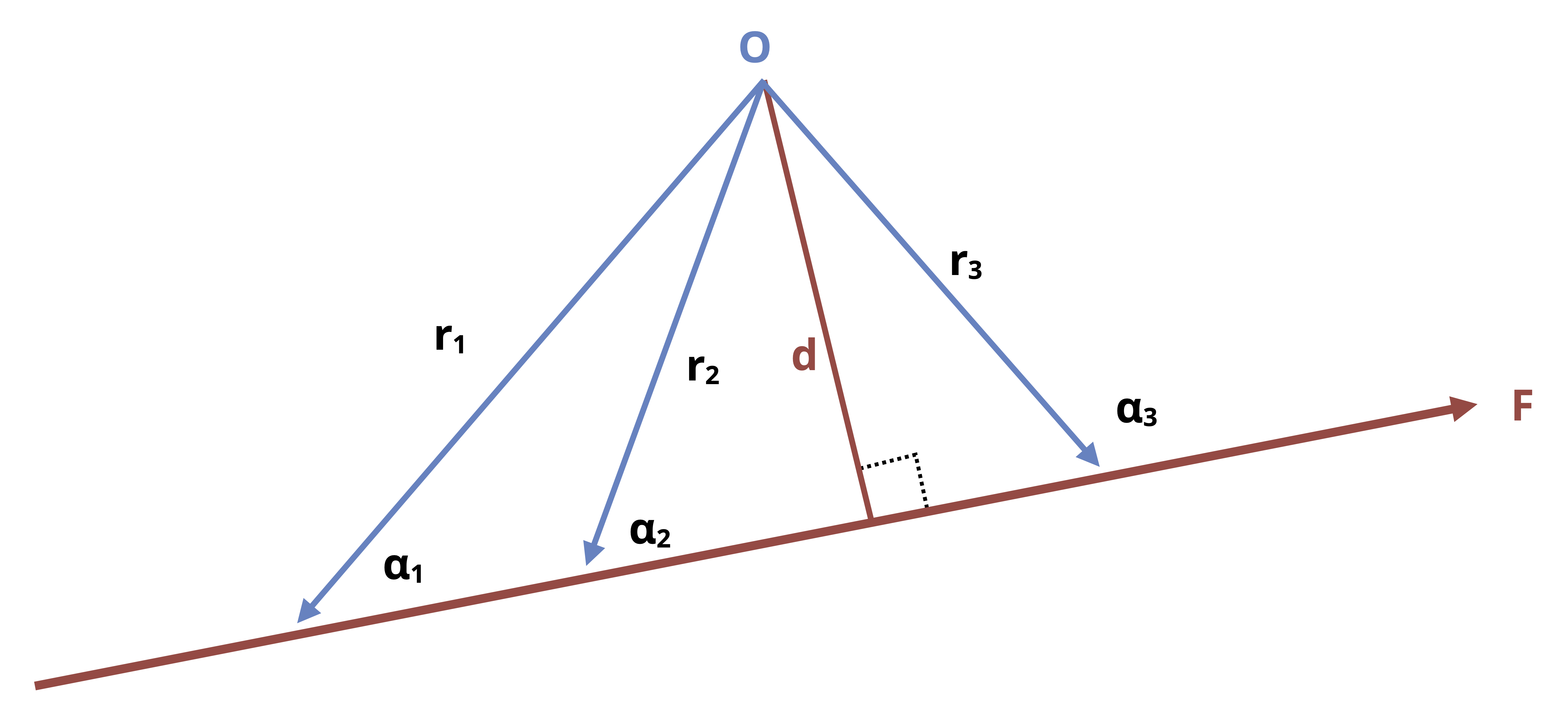
Any position vector that goes from the point the moment is about to any point on the line of action of the force (F) will work for \(\vec{r}\) in the cross product. Considering Figure 1.8, we could say
\[ \begin{aligned}\vec{M_O}&=\vec{r_1}\times\vec{F}\\&=\vec{r_2}\times\vec{F}\\&=\vec{r_3}\times\vec{F}\end{aligned}\\ \]
Using the cross product to calculate moment will result in a vector expression for the moment equation that gives all three components at one time with the correct signs to indicate clockwise (negative) or counterclockwise (positive) rotation. The direction of rotation depends on the perspective, here taken from the positive end of the axis looking toward the negative.
The second option to calculate moments is to perform scalar calculations in which the sum of the moments about the x-, y-, and z-axis is calculated individually. To use this option, it might be helpful to recall several concepts:
The general scalar equation for moment is M = F⨉d, where d is the perpendicular distance between the point the moment is being taken about and the line of action of the force (see Figure 1.8). You can also use
\[M=Fr\sin (\alpha),\]
where
r = any straight-line distance from the point the moment is being taken about to any point on the force vector \(\vec F\)
α = angle between \(\vec F\) and the position vector \(\vec{r}\) that corresponds to the distance r.
Figure 1.8 shows various α and r pairs. Note that either α or its complement angle can be used because the sine of the angle is the same either way.
Forces do not cause moments about points they traverse or axes they act through.
Forces do not cause moments about axes they are parallel to—for example, Fx wouldn’t cause a moment around an x-axis no matter where the point is.
When taking the moment about a point, move the origin of the coordinate axes to that point to determine the distance between the axis and the force.
Given all the foregoing reminders, you can apply the following equations:
\(\sum M_x= \pm F_y * z \pm F_z * y\), where z and y are the distances from the x-axis at the point in question to Fy and Fz respectively.
\(\sum M_y= \pm F_x * z \pm F_z * x\), where z and x are the distances from the y-axis at the point in question to Fx and Fz respectively.
\(\sum M_z= \pm F_x * y \pm F_y * x\), where y and x are the distances from the z-axis at the point in question to the Fx and Fy respectively.
The ± is decided by the right-hand rule or visual inspection. As mentioned, when using visual inspection, judge the direction of rotation by looking from the positive end of the axis toward the negative end. A counterclockwise rotation is considered positive, and a clockwise rotation is considered negative.
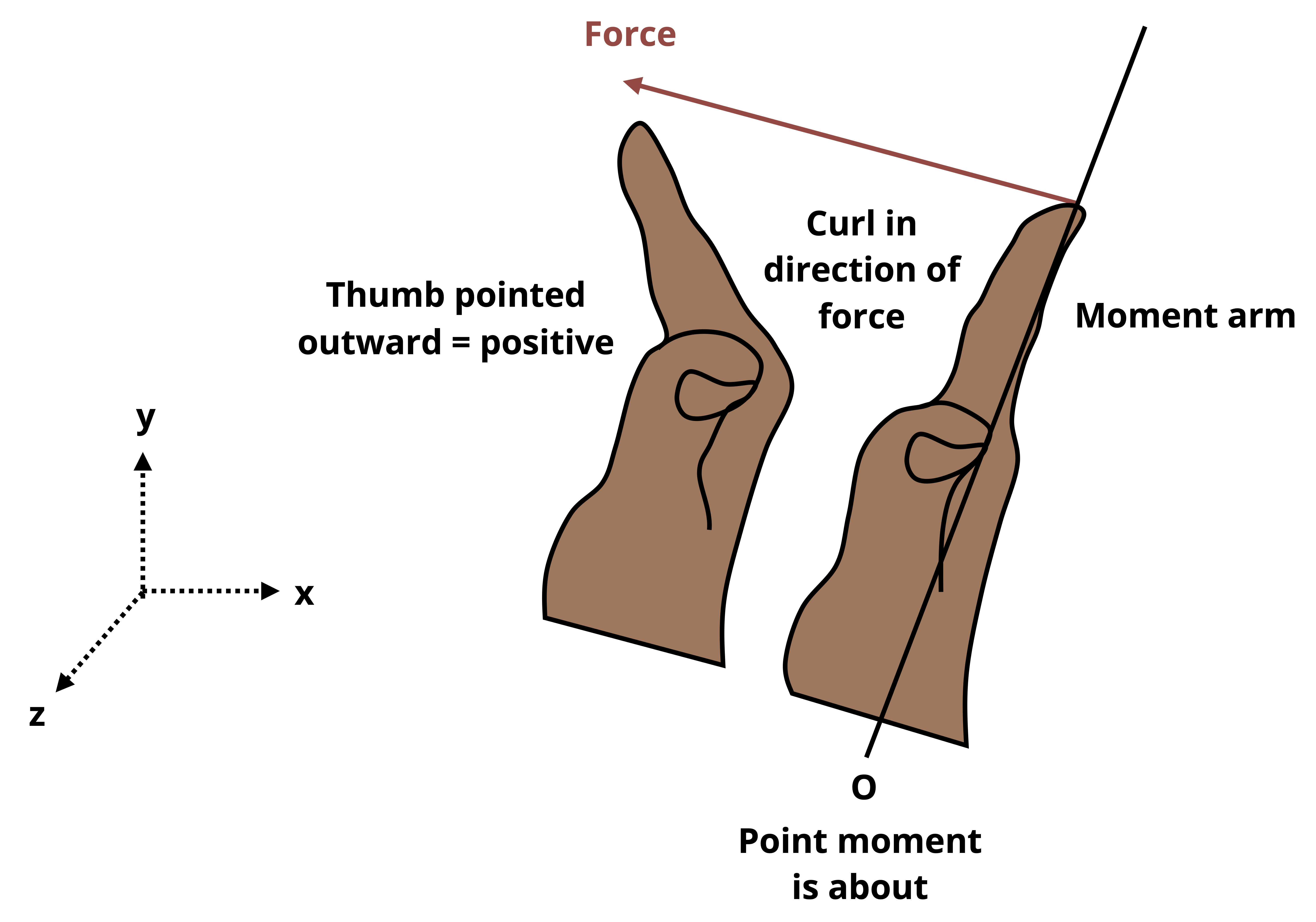
Take these steps to apply the right-hand rule:
Orient your right hand so that the palm is at the moment point and the fingers are aligned with the moment arm, extended to the force. The moment arm is the axis along which the perpendicular distance to the axis would be determined. For example, if finding Mx due to Fy, the moment arm is in the z direction.
The thumb is aligned with the axis of rotation—that is, with the axis around which the moment is being calculated.
Curl your fingers in the direction of the force. If to perform this action your thumb is pointed in the positive rotation axis direction, the moment is counterclockwise. If your thumb is pointed in the negative rotation axis direction, the moment is clockwise. Typical convention designates counterclockwise rotation to be positive and clockwise to be negative.
These concepts are further reviewed in Example 1.6.
Example 1.6
Determine the internal reactions at point P, located at the center of the cross-section of the rectangular bar and 1.75 ft from the fixed support at the origin. Let F = -150i - 225j + 300k lb.
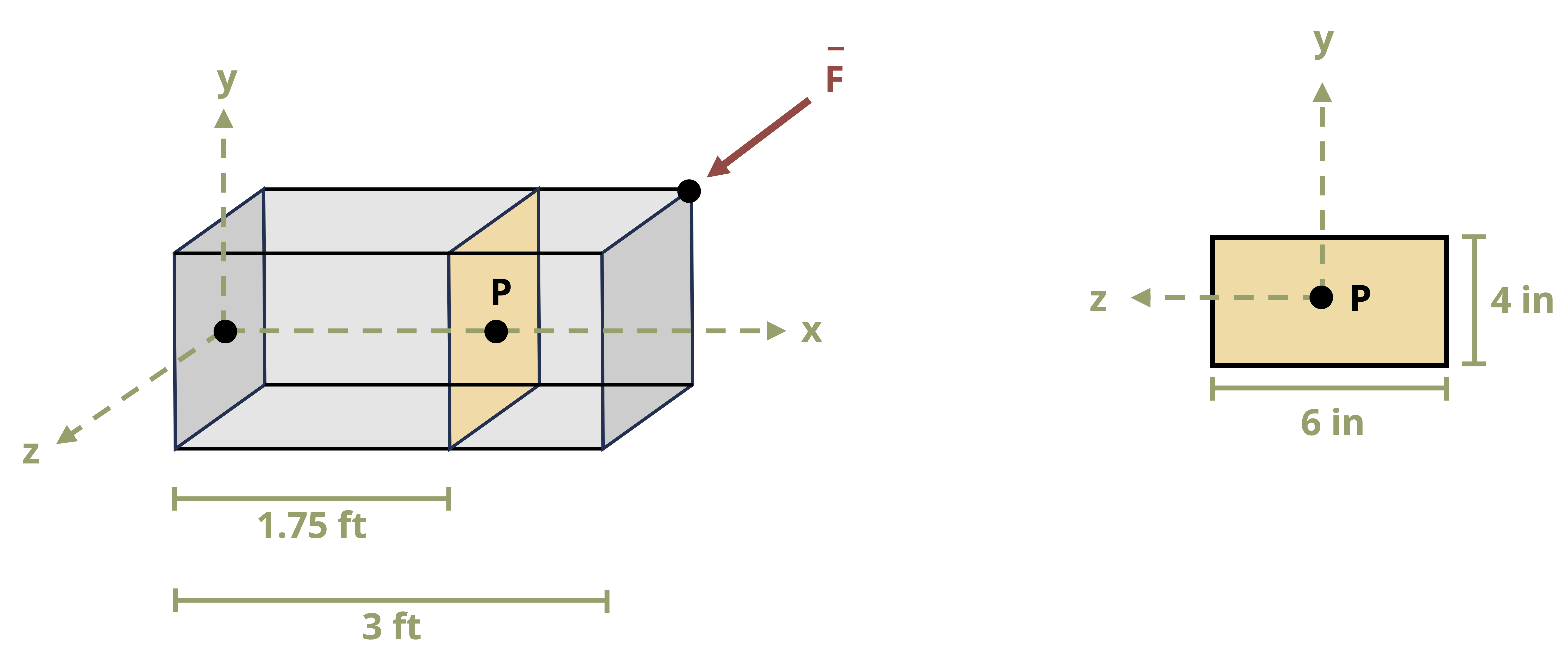
To determine the internal reactions at P, a cut is made at P that is parallel to the cross section. The section to the left of the cut includes the wall but the section to the right of the cut has no support. We will draw the FBD of the section to the right of the cut to avoid needing to know the reaction at the wall.
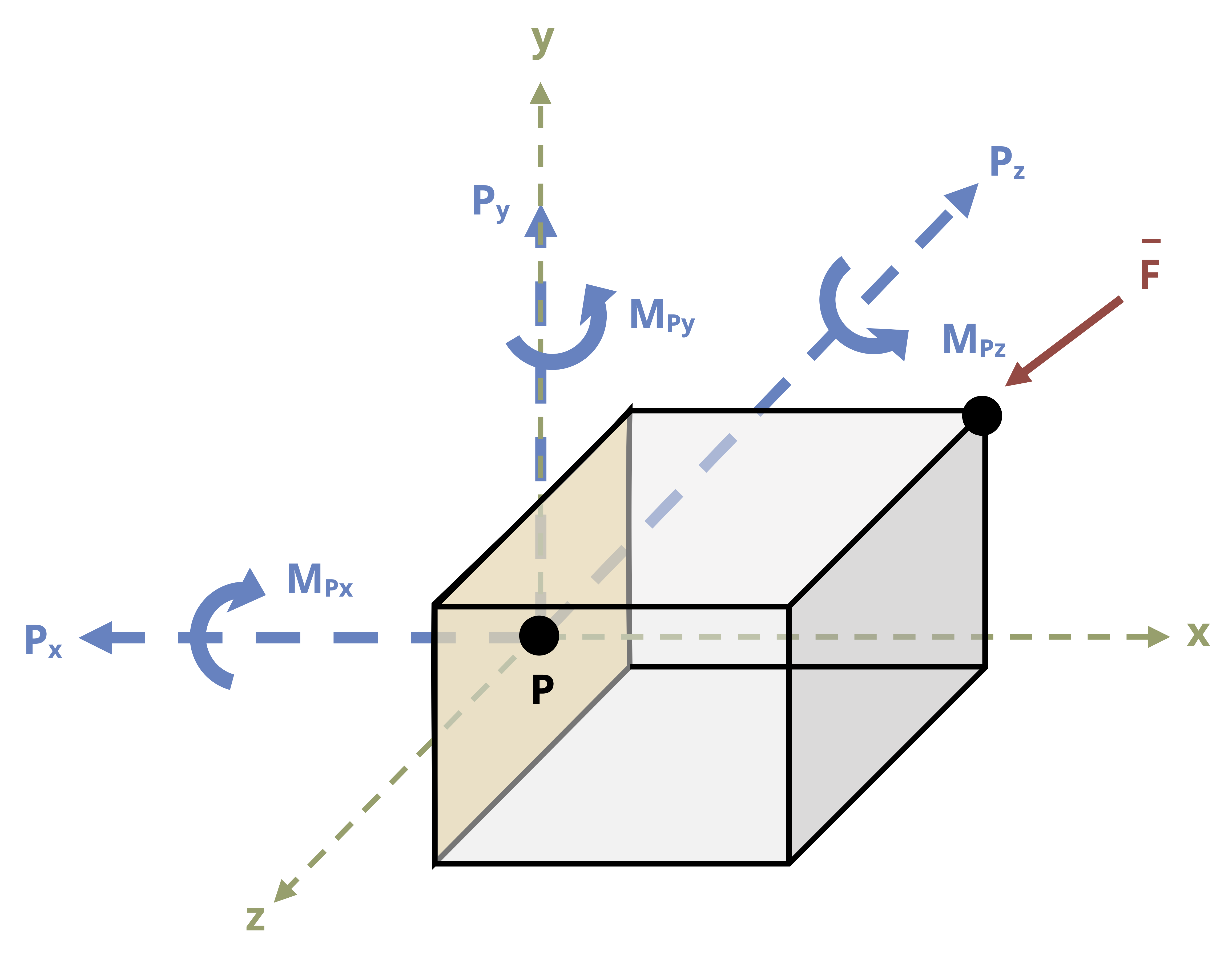
The x direction is normal to the cut section, so Px is the internal normal force reaction. Py and Pz are the internal shear force reactions.
The force reactions Px, Py, and Pz at P can be found by applying the force equilibrium equations.
\[ \begin{aligned}\sum F_x &= -P_x + F_x = 0\\&=-P_x-150\ lb=0\quad\rightarrow\quad P_x = -150 lb\end{aligned} \]
Px was assumed tensile (pointed away from the cut section), so the negative answer here means the force is compressive.
\[\begin{aligned}\sum F_y &= P_y + F_y = 0\\&=P_y-225\ lb=0\quad\rightarrow\quad P_y = 225 ~lb\end{aligned}\]
\[\begin{aligned}\sum F_z &= -P_z + F_z = 0\\&=-P_z+300\ lb=0\quad\rightarrow\quad P_z = 300 ~lb\end{aligned}\]
Note that shear direction forces are not designated as “tensile” or “compressive” since shear forces do not extend or compress a body. Signs on shear forces are discussed in Section 14.1.
The internal moment reactions MPx, MPy, and MPz can be found by taking the moments about point P. The sign on the individual multiplicative terms in each equation are determined by the right-hand rule or visualization.
The moment about the x-axis at point P is
\[ \sum M_{Px} = \pm ~F_yz \pm F_zy = 0 = -[(225{~lb})(3{~in.})(\frac{1{~ft}}{12{~in.}})]+[(300{~lb})(2{~in.})(\frac{1{~ft}}{12{~in.}})]-M_{Px}=0\\[20pt] M_{Px}= -6.25{~lb·ft} \]
The reaction MPx is subtracted because it is drawn on the FBD as counterclockwise around the negative x-axis, which means it is assumed clockwise around the positive x-axis. The negative answer means the reaction moment is opposite of the assumed direction, so it is actually counterclockwise around the positive x-axis.
The moment about the y-axis at point P is
\[ \sum M_{Py} = \pm ~F_xz \pm F_zx = 0 = (150{~lb})(3{~in.})(\frac{1{~ft}}{12{~in.}})-[(300{~lb})(1.25{~ft})]+M_{Py}=0\\[20pt] M_{Py}= 337.5{~lb·ft} \]
The reaction moment MPy is added because it is drawn counterclockwise around the positive y-axis. The positive answer means it is actually counterclockwise.
The moment about the z-axis at point P is
\[ \sum M_{Pz} = \pm F_xy \pm F_yx = 0 = [(150{~lb})(2{~in})(\frac{1{~ft}}{12{~in}})]-[(225{~lb})(1.25{~ft})]-M_{Pz}=0\\[20pt] M_{Pz}= -256.25{~lb·ft} \]
Like MPx, the reaction moment MPz is subtracted because it is drawn on the FBD as counterclockwise around the negative z-axis. The negative answer means the reaction is actually counterclockwise around the positive z-axis.
Answer:
Px = 150 lb (compressive)
Py = 225 lb
Pz = 300 lb
MPx = 6.25 lb·ft (counterclockwise)
MPy = 337.5 lb·ft (counterclockwise)
MPz = 256.25 lb·ft (counterclockwise)
Summary
Click to expand
References
Click to expand
Figures
All figures in this chapter were created by Kindred Grey in 2025 and released under a CC BY license.